How to make a roof at home with your own hands. How to make a roof at home: construction device and construction technology Installing a gutter system
To learn how to make a roof with your own hands correctly, you need to study a few instructions for doing this rather complicated job. It should be noted right away that there are several types of roofs, each of which has its own device scheme and requires a special approach. In addition, the choice of the type of roof will depend on the purpose of the building that will be covered by it.
Properly erected roof elements will be able to protect the house not only from precipitation, but also keep precious heat inside the building in winter. Therefore, a well-built and insulated roof is no less important than reliable warm walls.
Roof types
As mentioned above, there are several types of roofs. When choosing an option suitable for a particular building, it is worth considering some of them in order to know what they are.
 Various types roofs...
 To date, the following main types of roofs are satisfied in construction practice: single-pitched, gable with a slope, tent, mansard, hip four-pitched, half-hip, multi-pitched.
 … from the simplest to the most complex
 shed roof
This option is usually used to cover garages or outbuildings, but sometimes such a roof is also suitable for residential private houses.
Such a design can be called one of the simplest of all existing ones, especially in cases where the slope of the slope is very small. If there are plans to equip another room under the roof, then the design becomes somewhat more complicated. Nevertheless, this type of roof is the most economical in terms of roofing and lumber consumption.
Gable roof
The gable version of the roof is considered traditional for residential buildings, country houses and is installed more often than all other types. Apparently, this is due to the fact that such a roof can be arranged for any structure of the building. The slope of the slopes will depend on the distance between the outer walls and the location of the load-bearing walls inside the house.
hipped roof
This is a fairly complex design, which is almost never used in recent years. However, if it is decided to choose it, then it is better to use a beam-tightening system with struts and racks for the device.
The roof consists of four isosceles triangles - their vertices converge at one point. The hipped roof resembles a tetrahedral pyramid or tent, hence its name.
Double pitched roof
Such a roof is arranged according to the scheme of a gable roof, but it has bevels of different slopes in the front part.
Hip or pitched roof
This design is somewhat reminiscent of a hip roof version, but, unlike it, it has a ridge. The roof is quite complex in design, and most often a scheme with double puffs and beams is used to build it.
Half hip roof
This design in last years almost never used, as it is rather complicated in the device. If it is chosen, then it is mainly arranged according to the truss scheme with puffs.
pitched roof
Such a roof is arranged in houses with complex layouts, or if an extension is made to the main building. The design of a multi-pitched roof is quite complex, and it is used only in extreme cases.
mansard roof
 mansard roof you can’t call it simple in execution ...
 Due to the fact that this design allows you to solve two problems at once - to get an additional room at the same time as a reliable roof, the attic version can be called one of the most popular after the gable type.
 ... but under certain conditions, a residential attic can also be located under a conventional gable roof
 Roof pitch
It is very important to make the correct slope of the roof - the durability of not only the structure covering the house, but the entire building will depend on this. In regions with cold winters and a lot of snow, the slope plays a particularly important role, since if it is insufficient, then snowdrifts will collect on the surface, which, when melted, can simply fail the roof. That is why it is recommended to make the slope at least 40 ÷ 45 degrees.
In addition to the location of the building, the roofing material also affects the choice of roof slope. So, if it is planned to use tiles or slate for covering, then the slope should not be less than 25 degrees, otherwise water may seep into the attic at the joints, as there will be a small intensity of water runoff.
When constructing a gable structure, the slope is usually made from 30 to 45, and for a single slope 25 ÷ 30 degrees.
Components of the roof structure
IN different systems roof elements vary, but the main ones still remain the same. These include the following:

- Skate - the upper part of the roof, the place where its slopes are connected. This element is absent in the tent and single-sided version.
- Slopes are the main planes of the roof, covered roofing material.
- Endova - the inner corner of the roof, formed at the junction of two slopes. This element is present only in complex structures. When arranging the roof, valleys should be given special attention during waterproofing work, since such a site is one of the most vulnerable places in the structure, it is in them that the largest accumulation of snow occurs.
- The eaves overhang is the overhang of the roof on the sides of the house. They are installing drainage systems.
- Gable overhang - the protruding part of the slopes above the front side of the roof.
- The rafter system is a structure that is the basis for the installation of slopes. There are several varieties of these systems, but the most reliable of them is the triangle, since it is this figure that gives the structure rigidity.
Rafter systems
Before installing any structure made of wood, the material must first be coated with antiseptics and fire retardants, which can protect it from fungal formations, insect colonies and increase the fire safety of the entire system.

The main element in the rafter system is the rafters laid on the Mauerlat, supported by racks, fastened with beds and puffs.
In the upper part, the rafters are overlapped and fastened, while the lower ones are fixed to the Mauerlat or to the bars laid between the rafters.
The truss system has different forms and it can be layered or hanging.
You can make a simplified version when a crate is stuffed on the rafters, and roofing material is immediately laid on top of it. But the very first winter will show that the roof requires insulation. Therefore, it is best to immediately do everything right and not return to this issue again.
 Approximate structure of the "sandwich" of the insulated roof
 - The first thing that is recommended to be done is to sheathe the truss system from the inside with a vapor barrier film. It is stretched and attached to the rafters with a stapler and staples.
- Further, on top of the vapor barrier film, the roof from the attic side is sheathed with drywall plates - it is screwed with self-tapping screws. Drywall will not only give the attic space neatness, but also serve as the basis for insulation boards.
- At the next stage, you will have to climb the roof so that between the rafters, on the vapor barrier film, lay a heater, which is most often mineral wool in mats or rolls.
- A boardwalk is laid on top of the insulation. The boards for it should not be too thick so as not to make the structure heavier. Instead of boards, plywood sheets (or OSB) 4-5 mm thick can also be used.
- Sheets are next. waterproofing material- it can be a dense polyethylene film or roofing felt. The waterproofing sheets are overlapped by 20 ÷ 25 cm on top of each other.
- On top of the waterproofing, a counter-lattice is arranged, which consists of slats 10–20 mm thick and is stuffed directly onto the rafters.
- By counter-lattice fixed roof sheathing, with a distance between adjacent guides, which should be less than the tiles, by about 5 mm.
- A frontal board is nailed along the eaves, to which a drain system will later be arranged.
- Before laying the roofing material, hooks are fixed to the rafters, on which drainpipes will be mounted. gutters. After their installation, a cornice strip is installed, which is fixed to the frontal board
- Having arranged the crate and drainage system, you can proceed with the installation of tiles. It starts from the right or left side of the roof, from the bottom row, the tiles are aligned along the edge of the eaves and overlapped, in accordance with the locking system available on it.

- The second row of tiles begins to be laid on the same side as the first - it covers the first row by 50 ÷ 70 mm. Installation is carried out in the same order, up to the roof ridge.
- Having completed laying on the roof slopes, it is necessary to install a ridge at their junction.
- An end bar is fixed to the side rafter, having a size of 25 × 50 mm, and is installed on the corner of the roof corner - stub.
- A self-adhesive sealant is placed between the end bar and the tile.
- The entire side of the roof is closed with an end plate, which is designed to protect the roofing material from wind, which can tear off the coating with strong gusts.
Above, the process of arranging the under-roofing system and roofing with tiles was outlined briefly, with a simple enumeration of the main steps. It probably makes sense to consider it in more detail, literally step by step.
Prices for different types of tiles
roof tiles
Step-by-step instructions for covering the roof with a tiled roof
Installation of the base under the roofing material
Nowadays, a very wide variety of different roofing materials is presented on the construction market. Nevertheless, tile against this “background” does not lose its popularity, although it is one of the most complex and time-consuming roofing installations.
Ceramic tiles are represented by several European and domestic companies, and it may differ in some design nuances. But the principle of mounting the crate and the coating itself is the same.
For the installation and fixing of the tiles, it is necessary to create the correct basis - the crate, therefore, it is necessary to begin the consideration of the process with the installation of this particular design department.
| Illustration | |
|---|---|
 | On initial stage, of course, one of the types of truss systems is created, the design of which is described above. Before starting work on the installation of the batten on the rafters, the elements of the system must be additionally checked for their evenness and correct geometry. If irregularities are found on one of the rafter legs, then it must be leveled, since this flaw may adversely affect further work. The check is carried out using a perfectly even beam and a building level. |
 | The next step along the entire cornice line, a metal cornice strip is nailed to the edges of the rafters, which will protect the ends of the rafters from moisture getting on them. Separate planks are laid and overlapped. |
 | Further, above truss system the vapor-permeable membrane is stretched and fixed with staples. Its first canvas is laid from left to right on top of the cornice strip. |
 | The next strip of material is laid horizontally, overlapping 150 mm on the bottom sheet. The membrane is mounted with an inscription, which is applied to one of the surfaces, outward. Along the cornice edge, the canvas is additionally fixed on the cornice strip with the help of construction double-sided tape. |
 | The last top sheet should protrude above the ridge, as it bends onto the second roof slope. |
 | At the next stage, the vapor-permeable membrane is fixed from above to the rafter legs with counter rails. It should be noted that if the length of the slope is not more than 6000 mm, the thickness of the counter rail should be 24 mm, with a length of not more than 12000 mm - 28 mm, from 12000 mm - 40 mm. The counter rails should not reach the ridge rib by 120÷150 mm. |
 | Further, on the ridge at the top of the junction of the rafter legs, pieces of timber 150 ÷ 200 long and with a section of 50 × 50 mm are fixed. The space remaining between them will play the role of ventilation gaps. |
 | After that, the ridge is covered with a sheet of a vapor-permeable membrane, which should be on the slopes and go beyond the structure from the gables to a distance of 200 ÷ 250 mm. |
 | On top of the membrane, laid along the ridge, for its fixation, sections of the beam are fixed in continuation of the counter-rails. Their size should be equal to the distance from the end of the counter rail to the crest of the ridge. |
 | During the formation of the eaves overhang, a perforated mesh strip is mounted on the ends of the counter-battens and on the eaves strip, designed to provide ventilation of the space formed under the roofing material and protect against the penetration of various insects into this gap. |
 | Further, brackets are fixed in the eaves of the counter-rails for mounting gutters on them. Each of them is fixed with two screws or nails. |
 | In order for the gutter to be laid into the brackets without problems, they must be installed exactly in line with the formation of a slope for free flow of water. To do this, craftsmen often install two extreme brackets with the necessary difference, then pull a cord between them, and, already focusing on it, fix the rest of the hooks. |
 | After installing the brackets, a hinged beam is nailed along the cornice edge of the counter-rails along the entire length of the slope eaves. It also becomes the starting beam of the crate under the tiles. |
 | From the hinged beam on the extreme (at gables or roof profile fractures) counter-rails of the slope, the distance (step) with which the battens of the crate will be fixed is marked. This step will depend on the length and overlap of the particular shingle model. Most often it varies from 340 mm to 370 mm. Marking must be done on the extreme counter-rails. Then, on the marked risks, a nail is hammered in, a tracer colored cord is fixed and pulled on them, and with the help of it, a common line is beaten off on all counter-rails to secure the battens of the crate. |
 | The next step on the entire plane of the slope along the markings, horizontal battens of the crate are nailed to the counter-rails. Their cross-sectional size should be 70 × 30 or 70 × 25 mm. |
 | Upon completion of the installation, the crate should look like this. |
 | Next, it is necessary to prepare the roof ridge for further installation of ridge tiles on it - this can be done by attaching two beams to the ridge along the entire length, one on top of the other. |
 | Another option is to use special elements called ridge bar holders. They are screwed to the counter rails using two self-tapping screws on each side of the ridge. |
 | A wooden bar is installed and fixed in the fixed holders. Holders are convenient in that they can have different size and height, so you can always choose it according to the necessary parameters. |
 | Further, a gutter is installed and fixed in the brackets along the entire length of the eaves. |
 | The gutter is additionally pressed by another cornice strip mounted on the eaves rail. This element, fixed along the entire length of the eaves, closes the entrance to the under-roof space, thereby protecting it from moisture, and descends into the gutter. |
 | Further, on top of the crate along the edges of the slope from the side of the gables, bars with a section of 70 × 70 mm are nailed. They will become the basis for fixing the wind board from the gable part of the roof, as well as limit and close the edge of the tiled masonry. |
 | After that, wind boards are installed and fixed along the pediment, which are additionally interconnected in the ridge area with a metal corner. On this, the preparation of the crate for the installation of a tile coating can be considered completed. |
Installation of tiles on the prepared crate
Mounting of most models ceramic tiles almost identical, no matter what manufacturer's material is chosen by the owners.
| Illustration | Brief description of the operation to be performed |
|---|---|
 | Installation of tiles starts from the eaves on the right side of the slope. The corner tile is laid first, which is fixed to the second rail from the eaves. |
 | The first tile is fixed in the upper part with the help of two self-tapping screws that are not completely screwed in. |
 | Further, the entire first row of tiles is laid out, each of which is fixed in the upper part on the lathing rail with the help of one self-tapping screw through a hole drilled in it in advance. |
 | At the end of the first row of tiles, the last left corner tile is installed and screwed with two self-tapping screws. |
 | Further, from the bottom to the ridge, the first vertical gable row is mounted, consisting of corner tiles, each of which is fixed with two self-tapping screws. |
 | Next, you will need to prepare the tiles, which will be laid on top of the bracket for mounting a snow barrier on it. In order for the tile to neatly stand up and close the bracket, its location is marked on its reverse side and part of the lock is carefully knocked out with a hammer. |
 | Now, in the second horizontal row with a step of 900 mm, the brackets themselves are installed. This element is hooked with a hook and screwed to the third lath of the crate from the eaves. With the lower side, it is installed on top of the lower tile of the first row. |
 | Once installed and secured, the bracket should look like this illustration. |
 | Further, the prepared tile is installed on top of the fixed bracket and screwed to the third lath of the crate. |
 | The tile covering the bracket is additionally fixed with a wire hook, with which it is hooked to the side edge and twisted to the lath of the crate. In this way, every third tile of this row is fixed, which is laid on brackets-holders. In this illustration, a wire hook is clearly visible, located on the left edge of the tiles of the second row. |
 | Having installed the shingles of the second row, and having fixed all the brackets for the snow barrier, you need to try it on in place as it will be fixed later. It does not make sense to fix the barrier yet, as it will interfere with the further installation of the tiles. |
 | Further, laying of ordinary and corner tiles with an overlap is carried out, with their connection to locks, also from right to left, from bottom to top to those areas where additional elements necessary for the normal functioning of the roof structure are built into the coating. |
 | In this way, most often it is necessary to lay special ventilation tiles. If the roof has a length of up to 4500 mm, then these elements are not used. With a length of 4500 to 7000 mm, one row of ventilation tiles is mounted on the second row, counting from the ridge. On longer roofs, ventilation tiles are installed in three rows with a spacing of 1500 mm between them. |
 | On the third or fourth row from the ridge, in the middle part of the slope, a tile with a ventilation pipe, called a passage, is installed. |
 | In combination with other elements of the roof, this element looks like it is shown in this illustration. |
 | Having tried on this tile on a slope, it is temporarily removed, and a round hole is marked and cut out in the membrane under it. Then a sealing ring is installed in it. |
 | Further, from the attic side, a corrugated connecting pipe is inserted into the ring. Usually its diameter is 120 mm. Then, it is connected with the reverse side to the ventilation duct of the building. |
 | Top on ventilation pipe a protective cap is put on, which will protect the entire channel from atmospheric precipitation, dust and debris. |
 | Complete with tiles, a bench (step) for a chimney sweep is often purchased. This element of the roofing system is fixed on the fourth or fifth row from the ridge. The bench brackets are also of a hook design, and they are hooked and screwed to the top lath of the batten in the laying of the row. The lower side of the brackets is installed in the recesses on the tiles of the underlying row. |
 | In order for the closing brackets of the tiles of the upper row to fit snugly against the lath of the crate, chips are made in its locks located in the upper part after fitting. Then, the tiles are laid on top of the hook-brackets and fixed with screws and a wire hook - by analogy with what has already been discussed above. |
 | Another important and complex node when covering the roof is the design of the adjunction of the roofing material to the walls of the chimney. The joint between them must be sealed correctly and tightly. The most convenient way to work on the formation of the abutment is to use a flexible self-adhesive tape made using lead and aluminum. It well accepts a relief form of a tile and is well pasted to it. Adjacency finishing works are carried out in a certain sequence. First, the tape is glued to the front of the pipe with a call to its side walls, as well as to the tiles of the row passing in front of the chimney. To do this, in place, cuts of the desired shape are made on the tape. Then, it is measured and cut off, and then the tape is glued to the side walls and the tiles adjacent to them. |
 | To form a joint on the back side of the pipe, two pieces of tape of the same length are taken, which exceeds the width of the pipe by 20 ÷ 30 mm. They are glued to each other in width. Then, having combined the middle of the tape and the width of the pipe at a height of 150 ÷ 200 mm, the waterproofing is glued to the wall of the chimney and onto a metal sheet, previously fixed to the crate on the upper side of the pipe. After that, on a tape glued to the metal, a row of tiles is laid on top. The parts of the tape protruding at the corners are cut, wrapped on the sides of the pipe, and overlapped on the waterproofing already fixed to them. |
 | Some craftsmen prefer to decorate the junction with sheet metal, which is cut into strips of the desired width, mounted according to the same principle as a self-adhesive waterproofing tape. The connection of the edges of the metal at the corners is carried out with the help of rivets and folding. |
 | Having fixed a waterproofing tape or a metal casing around the entire perimeter of the pipe, along its upper line on the pipe walls, a metal profile bar is fixed, pressing the flexible tape to the surfaces of the chimney. Then, the gap remaining between the upper edge of the plank and the wall of the chimney pipe is filled with a roofing sealant. Often a groove is cut through the wall of the pipe, into which the bent edge of this metal tide is inserted. Then the shtraba is sealed with the same sealant. |
 | Next, proceed to work on the ridge knot. First, a perforated sealing ventilation tape made using aluminum and lead is laid on the fixed ridge beam overlapping the top row of tiles. |
 | Due to its flexibility, this ribbon skirt perfectly adapts to the shape of the tiles without much effort. |
 | After the tape has been laid, the end ridge element is screwed from the gable side of the ridge, and the first ridge tile is tried on to it. |
 | Further, the first tile is removed, and a ridge clamp with a bracket, which comes with the ridge tile, is screwed to the beam fixed on the roof ridge. |
 | Then the first ridge tile is installed in it. Further, it is fastened on the other side with the next clamp using a self-tapping screw. |
  | The next step is to install the second tile into the fixed bracket, which is also fixed at the end with a clamp - and so on, until the ridge is fully formed. |
 | When finished, the roof ridge should look like the one shown in this illustration. |
 | The final stage in the design of the ridge is the fixing of the second end element. If necessary, the last tile of this row is cut to the desired size. |
 | When all the additional elements of the roofing are installed, the last step to the brackets installed at the bottom of the slope is to fix the lattice barrier that prevents snow from slipping. |
 | This illustration shows a view of the finished roof slab as viewed from the eaves side. |
 | This is how the roof slope will look with all the elements installed on it. |
After completing the roof covering, you can move to the attic to remove the temporary decking and lay the already stationary wooden floor. Installation begins to be carried out from the side of the attic or from the side of the room. The attic floor also consists of several layers and is arranged in different ways. The main thing is that if the roof is arranged, then work can be carried out slowly, without fear of precipitation on permeable materials and inside the premises.
In conclusion, it is worth emphasizing once again that the installation of a roof is a laborious, responsible and rather dangerous process. Therefore, to carry out the installation of the entire roofing system, it is sometimes better to invite specialists who are professionally engaged in the construction of houses, arrangement and roofing.
More and more people are striving to realize their innermost dream - to get out of high-rise urban development in own house. Acquired suburban area quickly turns into a construction site. And, in accordance with the natural mentality of most Russian men, the construction of a new home is very often carried out on their own. And, many of the amateur craftsmen do not have much experience in this area at all, they learn literally on the go, they are looking for useful and reliable information in available sources, including on the pages Internet resources dedicated to construction. We hope that our portal will provide them with serious assistance in this matter.
So, after the walls of the house are raised on a reliable foundation, it is necessary, without delaying this, to proceed to the creation of a roof and roofing flooring. There can be many options here. And one of the most commonly used is a gable roof structure. It is not as complicated in calculations and installation as some others, that is, even a novice builder should cope with it. Therefore, the topic of this publication is the construction of the roof of a private house with your own hands using the example of a gable truss system with
It should immediately be noted that the article does not give a ready-made "recipe". The goal is to demonstrate the principles of calculating a gable roof and the sequence of its construction. And a master with an appropriate estimate should already bring the recommendations received to his own, specific construction conditions.
General information about the design of gable roofs
The basic design principle of a gable roof is probably clear from its name. The roof of such a roof forms two planes converging along the ridge line and resting on the long walls of the house (along the cornice lines). From the end sides, the roof is limited by vertical gable walls. As a rule, both along the line of cornices and along the pediment, the roofing is somewhat let out, outside the building in plan, so that overhangs are formed that protect the walls from direct precipitation.

Most often, the slopes have a symmetrical shape. Sometimes they resort to asymmetry, when the slopes are located at different angles to the horizon and, accordingly, differ in their length. But these are isolated cases, and will not be considered in this publication.
The height of the roof in the ridge, that is, the steepness of the slopes, can be different - it all depends on the planned use of the attic, the architectural ideas of the owners, and the type of roofing used.
Gable roofs have proven their worth high reliability. And the relative simplicity of the design makes them so popular among private developers.
The external similarity of gable roofs does not at all mean the uniformity of the design of their truss systems. It is precisely in this matter that there can be significant differences, depending both on the size of the building and on its design features.
According to the principle of structure, the truss systems of gable roofs can be divided into two groups:
- If the rafters rest on the outer walls of the building and are interconnected in a ridge knot, then such a system is called a hanging system.

To give additional rigidity to such a design, the rafter legs of each pair are reinforced with horizontal puffs (contractions). Vertical racks supported by floor beams, or diagonally mounted struts can also be used.
- In the case when the design of the house assumes the presence of a main wall inside the building, a layered truss system is often used. The name speaks for itself - the legs "lean" on the racks, which, in turn, rest on a bed laid along upper end of the capital internal walls. And, this wall can be located both in the center and offset from it. and for large buildings, two can be used as supports interior wall. Several examples of layered systems are shown in the illustration below.

- However, a kind of "hybrid" of both systems is often used. The rafters in these cases, even without the presence of an internal partition, also receive support on the central post in the ridge knot, which, in turn, rests on powerful floor beams or on horizontal puffs between the rafter legs.

In any of the systems, especially in cases where the rafter legs are of considerable length, additional reinforcement elements are used. This is necessary to exclude the possibility of deflection of the beam or even its fracture under the action of loads. And the loads here will be considerable. First of all, it is static, due to the weight of the rafter system itself, lathing, roofing and its insulation, if it is provided for by the project. Plus, there are large variable loads, among which wind and snow come out on top. Therefore, they strive to provide for rafter legs required amount support points to prevent possible deformation.
Some of their reinforcement elements are shown in the design diagrams of the truss system:

The illustration above shows an example of a layered truss system:
1 - Mauerlat. Usually this is a bar rigidly fixed on the upper end of the outer walls of the building. It serves as a support and base for securing the lower part of the rafter legs.
2 - Lezhen. A bar attached to the internal partition of a building.
3 - Rack (another name is the headstock). Vertical support going from the bed to the ridge run.
4 - Skate run. A beam or board that connects the central posts and serves as the basis for securing the upper ends of the rafter legs.
5 - Rafter legs.
6 - Struts. These are additional reinforcement elements, through which you can reduce the free span of the rafter leg, that is, create additional support points for it.
7 - Lathing, which must match the selected roofing.
Prices for fasteners for rafters
fasteners for rafters

In systems hanging type reinforcement is made by installing horizontal puffs (pos. 7), which rigidly connect the opposite rafter legs, and thereby reduce the bursting load acting on the walls of the building. There may be several such delays. For example, one is installed at the bottom, closer to the Mauerlat level or even almost flush with it. And the second is closer to the ridge knot (e is often also called a crossbar).
With a large length of rafters, it may also be necessary to use vertical racks (pos. 3) or diagonal struts (pos. 6), and often both of these elements in combination. They can be supported by floor beams (pos. 9), as shown in the illustration.
It should be correctly understood that the shown schemes are not a dogma at all. There are other designs of truss systems. For example, it is often used to fasten the lower part of the rafter legs not to the Mauerlat, but to the floor beams that are extended beyond the walls of the house. Thus, the necessary

In the roofs of large houses, more complex schemes can be used. For example, the rafters are connected by additional longitudinal runs, which, in turn, are supported by vertical posts or struts. But it is hardly reasonable to take on the creation of such complex systems without having a well-established experience in this area. Therefore, we confine ourselves to the construction of fairly simple gable roofs.
Carrying out calculations of the parameters of a gable roof
The construction of the truss system and the arrangement of the roof on its basis should always begin with necessary calculations. What are the tasks involved?
- First of all, it is necessary to deal with the ratio "ridge height - steepness of the roof slopes."
- After that, it will be possible to accurately calculate the length of the rafter legs, both “clean” and full, that is, taking into account the planned cornice overhangs.
- The length of the rafters and the estimated pitch from the installation will make it possible to determine the cross section of the material suitable for their manufacture, taking into account the expected roof loads. Or, conversely, based on the available material, choose optimal step and place additional support points - by installing the reinforcement elements mentioned above.
The listed parameters will allow you to draw up a diagram and a drawing of the truss system as accurately as possible, correctly position all its elements. According to the existing scheme, it will be much easier to calculate how much and what material is required for installation.
- You will need to find out the total area of \u200b\u200bthe roof slopes. This is necessary for the purchase of roofing material, hydro - and vapor barrier membranes, insulation, if thermal insulation of the roof is planned. In addition, the area parameter is also important for determining the amount of material for arranging the lathing for the selected roofing.
To make it clearer during the presentation of the calculation procedure, the main quantities are schematically shown in the illustration below:

D- the width of the house (the size of its gable wall);
VC- the height of the roof in the ridge above the plane of the Mauerlat or floor beams, depending on what the lower ends of the rafter legs will be attached to;
A- the angle of steepness of the roof slopes;
WITH- working length of the rafter leg, from the ridge to the Mauerlat;
∆С- elongation of the rafter leg to form the planned cornice overhang;
W- installation step of the rafter legs.
Let's start with the above questions in order.
The ratio of the steepness of the slopes and the height of the roof ridge
These two quantities are closely related. AND Totheir calculation can be approached from different angles, taking certain criteria as initial ones.
- For example, the owners see their house with a high roof, something remotely reminiscent of the Gothic style of architecture. It is clear that with this approach, the height of the roof in the ridge increases sharply and, accordingly, the steepness of the slopes. True, it should not be forgotten that such roofs experience maximum wind loads, due to their pronounced “sail”. But the snow on such slopes will practically not linger. So it is worth considering these two factors initially. Perhaps, for an area closed from the winds, but with a predominance of snowy winters, this option will generally be the most acceptable.
 Steep slopes and a high ridge are pronounced - snow does not linger on such a roof at all, but the effect of the wind becomes maximum
 But do not forget that the longer the rafter legs, the more difficult the system itself will be in arranging, which will require a lot of reinforcing parts.
- Another consideration to make the roof higher very often becomes the desire to have a functional attic space, up to equipping it with a full-fledged living room.
For an attic room, of course, a broken truss system is preferable. But if, nevertheless, a gable is planned, then a lot of space is eaten up by corner zones along the line connecting the rafters with a Mauerlat. It is necessary to increase the steepness of the slopes (see above).
True, and here there may be an acceptable solution. For example, the Mauerlat is not located at the level of the ceiling, as in the "classic" version, but on the side walls, which are deliberately raised above the ceiling to a certain height. Then, even with a large steepness of the slopes, and without much complication of the design of the system, magnon can achieve very spacious attic rooms.
Prices for metal tiles
metal tile

By the way, this option will be considered below, when the story will go already about the installation of the truss system.
- It happens that the owners of the future home, on the contrary, make a decision about the minimum angles of roof slope. This may be due to material saving structures, lack of usable attic space, local conditions such as very windy but not particularly snowy terrain.

True, with this approach, we must not forget that any roofing has certain lower limits for the steepness of the slopes. For example, if it is planned to lay piece tiles, then it is necessary to ensure a steepness angle of at least 20, and for some models even 30 degrees. So if the plans already have one or another roofing, its characteristics should be correlated with the height and steepness of the roof.
So, how is the calculation carried out. As a constant value - a constant, we have the width of the house along the gable wall ( D). Using the well-known trigonometric formula, it is easy to find the height ( VC), based on the planned steepness of the slopes (angle A).
Sun \u003d 0.5 × D × tg a
It is clear that half the width of the building is taken to calculate a symmetrical gable roof, that is 0.5 ×D.
One more nuance. When calculating according to this ratio, the height difference between the heights of the ridge point and the Mauerlat plane is taken as the height. That is, the excess over the attic floor is far from always meant - this should be borne in mind.
The above formula is included in the proposed calculator.
Calculator of the ratio of the steepness of the slopes of a gable roof and the height of its ridge
Its advantages include the possibility of saving on roofing material and scaffolding, ease and speed of construction, low weight.
Disadvantages: not very attractive appearance and lack of an attic or its small size.
- gable- much more popular than single-sided.
Its obvious advantages are relatively low weight (compared, for example, with a four-hinged one), a fairly large attic space, the possibility of arranging an attic in the under-roof space, as well as an attractive, harmonious appearance. This type the roof is warming up sunbeams at both sides.
The roof does not have any particular disadvantages. One can only point to its relatively heavy weight and greater consumption of building materials than in the construction of a pitched roof.
For a gable roof, you need a ridge (one-pitched roof does not need it) and gutters to drain rainwater.
- hipped roof
This type of roof is not very popular, since its construction is quite complicated and in order to build hipped roof do-it-yourself skills are required.
The obvious advantages of this type of roof include its aesthetic appearance, a large attic space. The possibility of four-sided heating makes the attic very warm.
Among the disadvantages of this type, one should indicate its large weight and, as already mentioned, the complexity of construction work.
- Combined roof
An ideal choice for a multi-level building or a structure that is not quite rectangular in shape. It looks quite original, besides, it harmoniously fits into almost any area.
A combined type roof is much easier to build, since it can be built in separate sections: at the first stage of work, cover a terrace located on the second floor under one slope; then build a gable roof over the bedrooms; at the next stage, cover the protruding section of the kitchen on the ground floor, etc.
On the picture different types roofs: 1 - single-sided; 2 - gable; 3 - broken line or attic; 4 - hip (four-slope); 5 - tent; 6 - multi-forceps.
There are also hipped roof, which is four identical slopes in the form of isosceles triangles; the roof of Sudeikin and others.
With all the variety of types of roofs, their construction is based on several basic principles. Having caught them, you can independently build even the most complex roof.
The entire construction process is divided into several main stages. So, we will learn how to build a roof with our own hands.
Mauerlat mount
The foundation that takes over main part load, - Mauerlat. The whole roof is built on it. Beams with a section of 15x15 cm are used. They are installed parallel to the roof ridge.
For the strength of the roof and resistance to adverse weather conditions, the Mauerlat beams should be securely fastened, and this must be taken care of already when laying the walls.
For this purpose, a strong thick rope is laid between the blocks (bricks) at a distance of 1 meter, starting from the fourth floor. It's called katanka.
The middle part of the wire must be fixed in the brickwork, and the ends should be left hanging down. Their length should be sufficient for the subsequent tying of the timber. If plastering is planned, then the outer end of the wire will need to be mounted in the solution.

Photo: fastening the Mauerlat with wire twist
Mauerlat should recede from the edge of the wall by at least 10 cm. To protect the beams from decay, it is necessary to lay roofing layers under them.
Frame installation
To ensure sufficient strength of the roof, it is necessary to take care of the frame. The frame of the house is the rafters attached to the Mauerlat.
It should be borne in mind that with a beam length of more than 4.5 cm, it will be necessary to additionally mount the runs. Optimal size beams consider a section of 7x15 cm.
The rafters are attached to the Mauerlat using a special cutout, fixed with 20 cm nails. Kill them like this:
- the first is driven diagonally through the rafter into the mahuelat;
- the second is nailed in a similar way on the reverse side;
- the third nail is hammered perpendicularly from above.
Thanks to this technology, the rafter is firmly attached and does not move.
The upper part of the overlapping beams is attracted to each other in such a way that the edge of one beam overlaps the end of the other (parallel). They are fastened with nails or bolts.
Roof reinforcement
To reduce the impact of the expansion force on the Mauerlat and increase the strength of the roof, the rafter legs must be fastened together using beams with a cross section of 5x15 cm.
This structural detail is called the "crossbar".
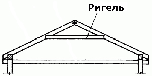 So, the size of the crossbar and the distance between the rafters to be connected correspond to each other. Fastening should be done with nails.
It is also necessary to take care of fastening to each rafter leg of the filly, which is a board with a section of 50x100 cm. It is fixed with metal brackets and screws to one side of the rafter leg.
Its length is calculated in the following way: 50 cm are added to the length of the overhang.
To avoid difficulties, you need to think in advance about harvesting filly. To do this, a cutout is made on the board, the width of which is 15 cm, with which it is attached to the Mauerlat.
Particular attention should be paid to ensuring that the boards and rafters converge exactly. It is better to complete all these works before the construction of the truss system begins, so that then you can simply assemble the entire structure.
At this stage, you also need to choose the value of the angle of inclination of the roof. For the correct choice, it is necessary to take into account the specifics of the area. For example, in the presence of heavy rainfall and a fairly cold climate, an inclination angle of 40 to 45 degrees is considered ideal.
On such a roof, snow does not accumulate, which avoids an increase in pressure on the floors. The distance between the rafter legs should be 1 meter.
In hot and dry climates, the minimum tilt angle is 3 degrees.
In areas with frequent strong winds The optimal angle of inclination is 20 degrees.
For an accurate calculation, you should use the rules used by professionals.
Builders measure this value using special tool- inclinometer. Before starting measurements, it is necessary to calculate the required angle.
For this, a special formula is used: the value of the angle of inclination is equal to the height of the ridge divided by the figure obtained by dividing the length of the roof by two.
crate
To cover the roof, you will need to make a crate. When choosing tiles as a roofing material, the crate must be continuous.

On the picture structural elements roofs: 1. roof roofing; 2. border; 3. ventilation hatch; 4. skate; 5. rafters ( rafter leg); 6. auxiliary elements; 7. counter beam (counter beam); 8. roof lathing; 9. safety protective element; 10. cornice gutter; 11. frieze (border) of the wall; 12. groove or valley; 13. drainage drain pipe; 14. snow-retaining fence; 15. vents for steam outlet; 16. support bridge; 17. anchor base plate; 18. strapping element; 19. lightning rod; 20. connection of technical equipment from the premises; 21. air duct; 22. access to the roof; 23. recumbent dormer (attic) window; 24. standing dormer window; 25. pipe (furnace chimney); 26. sloping roof slab; 27. attic floor; 28. dividing wall of the attic space; 29. thermal insulation.
For work, solid wooden boards are required, the thickness of which is approximately 25 cm. Particular attention should be paid to the absence of cracks and chips on them. The length of the boards should be equal to two spans between the rafters, i.e., be 2 meters.
In this case, the joints will be located only on the supports. The distance between them should be no more than 5 mm. The boards used to form the ridge should be placed as close as possible to each other. Fastening is carried out using nails 20 cm long.
The choice of lathing option depends on the type of roofing material.
If it is planned to create rolled soft roofs, then the lathing of the crate must be whole (solid). In the presence of a slate or metal roof, a discharged crate is suitable.
If necessary, you can make the flooring double. In this case, the first layer must be laid in the standard order - parallel to the ridge, and the second - along the slope, perpendicularly.
Ventilation
To cover the roof of the crate is not enough. You need to think about its integrity during operation.
In order for the tiles to be ventilated, it is necessary to leave gaps in the crate, two or three each. ventilation ducts from each side. Channels should start at the bottom of the overhang and end as high as possible. The width is approximately 5 cm. At the top, an outlet is installed under the hood to remove air.
Installation of drips and lining layer
To protect the roofing from the harmful effects of condensate on the crate, it is necessary to lay a lining layer. Its installation is carried out only along the edges, where there is a high probability of water seepage: on internal valleys, near pipes, to the ridge.
The width of the lining layer should be approximately 40 cm. The carpet is nailed with screws or nails at a distance of about 25-30 cm.
If necessary, you can lay another layer, it should be located on top of the already nailed one. You can glue the overlap with bituminous glue.
Another stage of work before covering the roof should be the installation of droppers. They are metal plates to protect the eaves from moisture.

The planks are nailed with nails at a distance of 10 cm, and the overlap is 5 cm. Droppers are fixed on the ridge in a similar way.
A flexible tile is attached to the plates, which helps to improve both the functions of the dripper and its appearance. Since the plates are self-adhesive, they must first be removed from the protective layer and only then attached to the eaves. For greater reliability, it is recommended to additionally nail them with nails.
Installation of roofing material
The choice of roofing material depends on the type of roof. Each option implies its own rules and installation conditions.
Flexible shingles
To facilitate overlapping and uniform distribution of tiles, the process should be started from the middle of the eaves. The protective film is removed from the shingle and glued to the base.
Then nails are nailed along the edges. The best option are galvanized nails with fairly wide caps. The joints of the shingle must be closed with ledges.
If the project assumes the presence of pipes, then special passage elements are attached along the perimeter of the shingle cut. The tile should be glued with an overlap in place of the ridge.
In the presence of a brick pipe that heats up, it would be better to put a triangular bar at the corner of the pipe and the roof. At a distance of about 20 cm from the pipe, a lining carpet is laid, and a special connector is put on the pipe. Cracks should be sealed with sealant.
metal tile
A discharged crate should be laid under the metal tile. The amount of material can be calculated by adding the length of the slope from the ridge to the eaves, the vertical overlap of the sheets and the eaves overhang.
The first of the sheets is laid and aligned along the end and eaves, the second should be laid on top, and the third on the side. Above the second sheet is the fourth.
The entire resulting structure must be leveled and attached to the crate using self-tapping screws. In accordance with this scheme, the entire roof is assembled.
External corners and ridge battens must be overlapped and fastened with self-tapping screws. Close the ridge from the ends with plugs.
Start covering the metal tile from the bottom, in the upper direction, from left to right. The tiles are preliminarily laid out in small (5 pieces each) stacks. They are placed on slopes.
In this case, the load exerted on the rafters is distributed evenly. Tiles are attached to the rafters with galvanized screws. On each of the sheets there are special wells, with which you need to attach the sheets to each other.
Cornice filing
This work is carried out on final stage. The walls should already be insulated, since the filing box should fit snugly against them. Otherwise, it will be necessary to either break the filing, or leave the wall section uninsulated.
Preferably, the lining is made of wood. So it will be possible not to carry out additional ventilation. The filing is a kind of box attached to the continuation of the rafters and the filly.

In the photo, the design of the cornice overhang
Its frame consists of two boards, one of which goes from the end of the overhang towards the wall, while the second goes down from the rafters. Boards are joined at right angles. Self-tapping screws or screws are used to fasten the joints.
Metal plates are also used. Leave gaps between boards small size. The corners of the box are cut at a certain slope, and they are fastened with metal brackets and self-tapping screws.
Then the lower part of the frame is upholstered with boards along the entire length. Since they are exposed to the environment, they must be fastened very carefully, especially at the edges. It is also necessary to pay attention to the fact that the joints of the rows of adjacent beams do not coincide. Corners need to be cut at 45 degrees.
Roof insulation
Warming is not less important point than the construction of the roof itself.
There are several options for insulation: from above and from the inside of the crate.
If the attic space will not be used as a living area, then it is possible to carry out internal insulation. It will also hide free space between the rafters.
First of all, it is necessary to cover the entire perimeter of the roof with a waterproofing film. Since the rafters are located on top of the crate, it is impossible to stretch the film with a canvas.
 It is necessary to ensure that the film covers all the details of the structure. Between the rafters and the crate, in the corners, nailed over the film wooden slats. Then it is necessary to nail to the crate between the rafters mineral wool. The plates of this insulation must be laid end to end with each other.
The next layer is a vapor barrier film. Its lower edge must be attached to the rafters. The joints of two films (waterproofing and vapor barrier) must be superimposed on each other and tightly fixed with construction tape.
If the attic is planned to be used as a living space, then care should be taken to ensure that the roof is warmer.
In this case, the film and insulation must be laid on top roof structures and crates. The use of polyurethane foam boards should be avoided as this material cannot be joined tightly enough.
Mineral wool is the best choice as one layer. It is also necessary to use a waterproofing film. The principle of work on insulation is similar to that described.
It is more reliable to use mineral wool as one of the layers and be sure to use a waterproofing film. In fact, the principle of insulation work is not too different.
So, we build a roof with our own hands
To build a roof of a house with your own hands, you need to follow the following steps:
- Fixing the Mauerlat;
- Installation of rafters;
- crate;
- Installation of droppers, lining layer;
- Installation of roofing material;
- Cornice filing;
- Roof insulation.
We offer you a video about the roof:
In this article I will try to describe in detail how a gable is being built. This form is practically the simplest, suitable for a private house and its construction, from the point of view of monetary costs, is more profitable compared to other more complex roof configurations.
- in the second case, the rafters lie on the floor beams of the floor below. A gable roof made according to this option will be described here.

Let's take a brick box at home as an example. Its dimensions are 8x8 meters, height 3 meters. Do-it-yourself construction of any roof begins with the installation of a maurlat (Fig. 1). Methods for attaching it to the walls were described in the article, which you can read.
Mauerlat install flush with inner surface walls. Outside, it must be bricked up so that it cannot be seen. At the same time, the upper surface of the Mauerlat should be 2-3 cm higher than the upper surface of the facing brick, so that the entire load from the roof is transferred only to the Mauerlat. No need to load .

Next, install the floor beams. We do this in the sequence indicated in Fig. 2. First of all, we put the beams indicated by the numbers 1,2,3,4. Their removal determines the width of the eaves. We usually take it from 40 to 50 cm at the request of the customer. As beams, we use a beam, the section of which is determined by making a simple calculation described in detail. In our case, it will be a beam of 100x200 mm.
After fixing the extreme floor beams, we stretch the cord along the upper plane and expose the rest of the beams, if necessary, pulling up the Mauerlat under them, or vice versa, laying thin plywood (you just often order a beam 200 mm high, and they bring it from 190 to 210 mm, this is on our sawmills equipment). We choose their step taking into account the step of future rafters. When using floorboards 50x150 mm as rafters, we take a step of 60-70 cm (it is better to take 60 cm, because roofing insulation has such a width).
Having installed all the long beams, we put the short ones (Fig. 2). Their step is enough to make about 1 meter. This scheme is slightly different from what we are used to seeing in similar pictures. We came to it after the pediment tide sagged on one of our first roofs, although the tides of the tide were securely fixed. In this scheme, the possibility of sagging is completely excluded.
We fasten all beams to the Mauerlat with 150 nails, you can also use metal rafter corners and self-tapping screws. In general, the use of various fasteners for rafter connections makes it easier to work. This is especially convenient for an inexperienced person, you do not need to make complex cuts and notches. We have already talked about this in the article "".
After installing all the beams, we lay (without fixing) boards on them, you can floor, you can inches. They are needed just to walk on them calmly. In order not to clutter up the drawing, I did not show them on it. The next step is to install the ridge beam.

First of all, we set the racks from the board 50x150 mm according to the level or plumb and fasten them with the help of temporary struts. On fig. The 3 spacers are shown on only one post, again to keep the drawing clear. The step of the racks is not more than 3 meters. First we put the extreme ones, then, pulling the laces between them, we put the intermediate racks. After the construction of the entire truss truss, the intermediate racks can be removed and the living rooms can be easily made on the second floor.
The height of the racks is selected depending on what shape of the roof you want to get. I usually advise customers to take it equal to the height of the first floor along the facade (the distance from ground level to the Mauerlat). This proportion is also shown in the figures.
Having installed the racks, we put them on them and fix the ridge beam literally on a couple of screws. As it we use a board 50x200 mm (in principle, 50x150 mm is also possible).

Now we move on to the installation of rafters. First we need to make a template from a 25x150 board. To do this, we apply it to the end of the ridge beam and to the beam (Fig. 4) and draw two lines. Having sawed off a board on them, we get a rafter template.
Of course, it is very good when the foot of the house is laid out with high geometric accuracy and floor beams are also installed. Then we can cut all the rafters at once according to the template and install them calmly. But to be honest, this is quite difficult to achieve, and even more difficult when a new roof is being made on an old house.

In this case, we first make only the top notch at the rafter according to the template. Then we take the resulting workpiece, apply it to the desired beam and mark the bottom gash, as they say in place. All rafters are installed in this way (Fig. 5). Please note that having installed one rafter, we immediately set the opposite one to it in order to quickly remove the lateral load on the ridge beam (otherwise it will bend it).
When the length of the roof slope is large and the standard 6-meter board is not enough, there are two ways to go. The first (I think it is preferable) is to order longer boards at the sawmill. Of course it will cost more. For example, at the end of autumn 2012, we had 1 cube of 6-meter boards cost about 5,500 rubles, and 1 cube of boards 7.5 meters long cost 7,000. But installing rafters is easier and faster than using the second method.
 According to the second method, you need to splice two boards. This can be done by sewing on them a piece of board of the same section with a length of 1.5 - 2 meters. See the figure for how this is done. The joint is best done at the bottom, and under it it is necessary to install an additional rack.
We attach the rafter to the ridge beam with two or three nails. For fastening to the floor beam, we have recently been using metal mounting plates and self-tapping screws and adding a couple of nails. Sometimes we use brackets. By the way, I have seen many times how people use staples, but they do it wrong. The bracket must work in tension. Below on the left photo - how not to do it, on the right - how to do it.


Having strengthened the truss truss, we begin to deal with gables. First, we put additional racks, which will be the gable frame (Fig. 7). The accuracy of the installation is controlled by a cord stretched along the bottom of the rafters. Then we do window hole(Fig. 8). You can make it any size and configuration you like. Please note that in the figure, the stand in the center of the window (supporting the ridge beam at the beginning) was simply cut. It no longer bears almost any load. Having finished with the frame, we sheathe the pediment with an inch (for example, 25x150 mm) (Fig. 9).

The next step is filing the cornice boards around the entire perimeter of the house. The frontal board (sewn to the ends of the floor beams) is made from a board 25x200 mm. We hem two belts from the board 25x100 from below to the cornices (Fig. 10). They are more than enough to secure outdoor decoration soffit.
Now, if we are going to mount the drainage system and use metal holders for the gutters, they need to be installed on the stops right now (under the waterproofing film). Moreover, it is also desirable to sheathe the frontal boards with siding at this stage. Then it will not be very convenient to do this. I didn't show it in the picture. In addition, we now only use plastic gutter holders that are attached directly to the front board. It is more convenient with them and you can put them after the roof is assembled.

Next, we proceed to the crate. First of all, using a construction stapler, we fix the first strip of waterproofing film on the rafters (Fig. 11). It is more convenient to work if scaffolding is already installed around the perimeter of the house. In any case, you will have to put them when you make a roof, drain, sheathe the cornices with siding.
Having fixed the film, we nail the slats of the counter-lattice (25x50 mm) to the rafters. The need to use a counter-lattice is described in detail here: . Do not forget to leave room for the overlap of the subsequent waterproofing strip.

Then we make a crate. Now I will not focus on the rules for its installation. This topic is for a separate article. In addition, instructions are attached to any roof covering, which describes in detail how to make a crate specifically for this material (the figures schematically show a crate for a metal tile). I will try to prepare a new article on this topic in the near future.
In this way we cover the entire roof (Fig. 12). After that, it remains only to make a gable overhang and a gable ebb. The sequence here is:

To the protruding ends of the lathing with self-tapping screws, we hem the wind board of the gable overhang (25x150 mm) from below (Fig. 13);

We insert and fix the filly of the gable overhang with self-tapping screws (board 25x150). The distance between them is about 1 meter (Fig. 14);

We sew two belts to the fillies from below (board 25x100). They are also enough to subsequently sheathe the gable overhangs with siding (Fig. 15);

From pieces of the board 50x150 of the required length, we prepare triangular fillies for the gable ebb according to the figure (Fig. 16). Then, fixing them on the takeaways, we also nail two belts (25x100) to them.
This completes our roof. What happened in the end and what happens after the implementation roofing works and sheathing of the gable and cornices with siding is approximately shown in Figures 17 and 18.


The correct roof of the house implies not only a beautiful appearance, but also robust design
The construction of the roof of private houses is a difficult and very responsible job. The easiest option is to order turnkey construction from a specialized company, and expect a happy moment when you can move into a brand new house or cottage. But this method is good if there are enough funds to pay for the expensive services of builders-installers. It is better to build a house yourself, it will cost about half the price. This will require a quality project.. A properly designed project with calculations requires knowledge and design experience. So it's better to use either finished project, or order it from a specialized organization. Below we will dwell on the technology of building a roof. Installation and directly depends on its type and design. Therefore, first we will tell you what roofs are.
Roof types
The specifics and features of the roof largely depend on its type. Currently, there are many typical projects of private houses, with original and sometimes very spectacular roofs. Consider several common varieties that differ in their design:
- Shed. The simplest option looks like a right triangle in section.
- Gable. Sometimes called gable, a roof structure with two inclined planes. The attic room is perfectly built in here.
- broken line. A variation of the previous type, having slopes with a break (changed angle). A large number of modern houses can be seen precisely with a sloping roof.
- Hip (semi-hip). A four-slope design that allows you to raise the ceiling and conveniently place an attic under it.
- Conical or domed. Generally best suited for polygonal or circular buildings.
- Multi-forceps. A non-standard design, as well as a variant with a broken roof, requires painstaking calculation. Only an experienced architect is able to make a good project, and the cost of work is very high.

 Various types of roofs for country houses and cottages
 The rafter system forms the roof frame, which is the skeleton that ensures the reliability and strength of the entire structure of the house. The frame determines the type and shape of the roof of the building, its task is not only to support the roofing, but also to evenly distribute the load on the walls of the house. Right choice rafter systems, its competent construction will ensure the reliability of the structure, its durability and strength.
The truss system is constructed, as a rule, from coniferous wood, well dried to a moisture content of 18-23%. It is possible to make a good and durable roof only from high-quality material.
When calculating loads, it should be taken into account that two types of forces act on the frame: constant and variable:
- The constants include the weight of the entire frame structure, together with the drainage system, insulation and roofing.
- The variables are the weight of people inside, snow cover and wind pressure.


Important!
The calculation of live loads is carried out on the basis of building codes for the climatic regions of Russia.
We will consider the components and elements of the frame using the example of the most common design with 4 slopes:
- Mauerlat, timber, laid on top of the walls of the house. It serves as a support for the rafters and evenly distributes the load on the building structure.
- Rafter, has another name rafter leg. An angled beam or board, with the lower part resting on the Mauerlat and the upper part on the girders. Determines the slope of the slopes, serves as a reference element to support the coating.
- Run. Horizontal beam to support the upper ends of the rafters. Can serve as a ridge beam. Mounted on vertical posts. It is better to make it from a bar or a thick board.
- Racks are vertical. They are a support for runs, located on load-bearing walls or on beds.
- Lie down. Beams laid horizontally on the walls of the house, playing the role of floor beams. They serve as a support for racks, carry vertical loads and the weight of the roof.
- Puffs. Boards fixing the rafters of opposite slopes, create rigidity of the structure, fix the rafters.
- Struts. Boards that perform a supporting function and protect the rafters from deflection.
- Wind beams. Boards fastening the rafters on one slope, fixed diagonally from the ridge to the Mauerlat. They perform the task of strengthening the frame and protecting it from wind loads.
- Filly. A board fixed on a Mauerlat, forming an overhang.
- Sprengel. A bar fixed at the corners of the house between the connecting Mauerlats of adjacent walls.
 truss system gable roof
 The listed parts of the frame take place in almost all types of truss systems, of which there are several types.
The rafter system is the basis of any roof, its skeleton. Its main purpose is to give the roof structure strength and reliability. In addition, it is designed to evenly distribute the load on the walls of the house. There are several types of truss systems that allow you to make a reliable roof:
- Hanging or suspended rafter system. With this design, there are no intermediate pillars to support the rafters, and the connection is made with wooden or metal puffs. In the upper part of the rafters rest against each other, and the load is transferred due to puffs. In this system, various forces act on the rafters: compression, bending and the vertical component, bending the rafter down.
- Layered system. As a rule, it is used in gable roofs. It is used with the use of intermediate supports or in the construction of houses with a central load-bearing wall. Rafters are installed with support at one end on the walls and the other on intermediate pillars. SNiP regulates a device of a similar design for gable roofs only in cases where the distance between bearing walls no more than 6.5 meters. The layered system is lighter and easier to install.
- Sloped roof rafter system. complex structure that requires good project and careful calculations. For broken structure it is possible to raise the roof and make the attic higher, and minimize the unused area.
 Roof options
 Often a combination of these roofing systems is used. It is important that the rafter scheme is calculated at the design stage of the building. According to the results of calculations carried out according to a complex methodology, it is necessary to obtain data on the loads per 1 sq.m of the rafter system. SNiP regulates the standard value of 50 kg per sq.m. Also, according to the results of calculations, you can choose one or another type of rafter system.
Farms in roof systems
It is best to make a rafter system from ready-made trusses assembled at the factory. Calculated according to all standards, made of high-quality and well-dried wood, trusses greatly facilitate and speed up the construction process.
The entire structure built using trusses is much lighter and stronger. Trusses reduce wall loads by transmitting only vertical forces. The lower belt of the trusses is designed so that it can serve as an attic floor beam. The convenience of using trusses lies in the ability to cover a large span without additional support.

 A roof truss made of wood is the most common option.
 Advice!
If the structure of your house is more than six meters or the roof according to the project is very flat (the slope is less than 30˚), consider whether it is better to use ready-made wooden trusses.
The disadvantages of this design are that it costs a little more than building it on its own, and there are also some difficulties in raising it to the desired height.
Roof design
As mentioned above, the key to a reliable and durable roof structure must be a well-designed project. As a rule, it consists of several sections and drawings. It contains calculations and all information about the roof structure:
- first of all, the project determines the main parameters - the shape of the roof, its dimensions, the slope of the slopes, the presence of a pediment;
- the second, and no less important point, is a list of all materials for each node, indicating their quantity;
- a separate section should be devoted to the calculation load-bearing structures indicating the section of the rafter beams, the dimensions of the floor elements and other nodes;
- drawings in various projections with details of the main units;
- a section with calculations of the thermal properties of the roof structure and instructions on insulation and waterproofing, with a list of recommended materials;
- recommendations for roofing material based on the calculation of the maximum loads on the structure.

 Roof design in accordance with SNiP
 An important section of the project should be the section on insulation, waterproofing and ventilation.
Important!
Properly equipped under-roof space will avoid the accumulation of condensed moisture and leaks.
Proper insulation will create comfortable conditions for staying inside the building. All taken together will increase the strength, durability and reliability of the roof and the entire building.
roof project
Thermal and waterproofing
An important detail for the roof insulation device is the fact that not only external weather factors act on the roof, but also internal ones:
- heat from the living quarters;
- evaporation;
- condensate formed from the temperature difference in the upper floor and outside.
Therefore, the requirements for roof insulation contain additional conditions compared to wall insulation. This is the laying of vapor barrier materials, a heat-shielding layer and waterproofing. In addition, it is necessary to equip effective ventilation roof space, otherwise constant dampness in the room threatens.

 Roof waterproofing is one of the mandatory stages of its arrangement.
 To reliably insulate the upper floor, mineral or eco-wool is usually used. In combination with a waterproofing and vapor barrier film, good protection against external and internal influences is obtained. A air layer between different insulators will ensure ventilation of gables and roofs.
Step-by-step instructions for ensuring moisture resistance and functionality of the roof
To keep the roof from blowing
An important nuance that must be taken into account during installation and during the reconstruction of the roof is its attachment system to the house. A once-in-a-century hurricane shouldn't lift and blow our roof off. For this, fastenings of the frame to the walls are provided. When choosing a method of fastening, it should be ensured that the truss system does not burst the walls.
If fastening is carried out in a stone house, then it is recommended to fasten the rafters with crutches driven in from the inside of the wall. Fixation is made with a wire tie in several turns. In some cases, you can fasten the rafters to the floor beams. Such fastening provides for a small backlash in the joints of the rafters with the Mauerlat, which avoids the expansion of the walls.
In addition, do not forget to install wind boards (see above) during installation and repair. Such a bundle protects against wind loads from the inside. Wind boards prevent structural vibrations that eventually lead to destruction.

 A roof with steep slopes can be overturned by strong gusts of wind, with gentle slopes - lift
 The crate is designed to hold the roofing. It is done at the last stage of the construction of the frame (truss system). If the floor beams are installed in the openings of the walls, then fillies should be fixed to the first rafters from the bottom, which will help to make the roof overhang. In cases where the ceiling is laid along the Mauerlat, there is no need for fillies, since the beams in this design protrude beyond the perimeter of the walls, thereby creating a roof overhang.
The type of lathing is selected in accordance with the planned roofing material. The crate is made either with small gaps, or solid, with the laying of the board close.
 An important element of the roof for the integrity and durability of the future roof is the crate - the foundation and guarantee of your peace of mind with its correct and reliable fastening
 We lay a layer of waterproofing on top of the crate. Now you can sew up the gables and proceed with the installation of the finish coating.
Roof repair: installation of lathing


