The maximum size of the water floor heating circuit. Maximum length of the underfloor heating water circuit: installation and calculation of the optimal value. Hydraulic pitch between turns
One of the conditions for the implementation of high-quality and correct heating premises with a warm floor is to maintain the temperature of the heat carrier in accordance with the specified parameters.
These parameters are determined by the project taking into account the required amount heat for the heated room and floor covering.
Required data for calculation

The efficiency of the heating system depends on a correctly laid circuit.
To maintain the set temperature in the room, it is necessary to correctly calculate the length of the loops used for the circulation of the coolant.
First, you need to collect initial data, on the basis of which the calculation will be made and which consists of the following indicators and characteristics:
- the temperature that should be above the floor covering;
- layout of loops with a coolant;
- distance between pipes;
- maximum possible pipe length;
- the possibility of using several contours of different length;
- connection of several loops to one collector and to one pump and their possible number with such a connection.
Based on the listed data, it is possible to perform the correct calculation of the length of the underfloor heating circuit and thereby ensure a comfortable temperature regime in the room with minimal energy costs.
Floor temperature
The temperature on the surface of the floor, made with a water heating device under it, depends on the functional purpose of the room. Its values \u200b\u200bshould be no more than those indicated in the table:
Compliance with the temperature regime in accordance with the above values \u200b\u200bwill create a favorable environment for the work and rest of people in them.
Pipe laying options used for underfloor heating

Underfloor heating installation options
The laying pattern can be done with a regular, double and angled snake or snail. Various combinations of these options are also possible, for example, along the edge of the room, you can lay out the pipe with a snake, and then the middle part with a snail.
In large rooms with a complex configuration, it is better to lay it with a snail. Indoors small size and having a variety of complex configurations, snake laying is used.
Distance between pipes
The pipe laying step is determined by calculation and usually corresponds to 15, 20 and 25 cm, but no more. When the pipe is laid out with a step of more than 25 cm, the person's foot will feel the temperature difference between and immediately above them.

Along the edges of the room, the heating circuit pipe is laid in 10 cm increments.
Permissible contour length

The length of the circuit must be matched to the pipe diameter
It depends on the pressure in a particular closed loop and hydraulic resistance, the values \u200b\u200bof which determine the diameter of the pipes and the volume of fluid that is supplied to them per unit of time.
When installing a warm floor, situations often occur when the circulation of the coolant in a separate loop is disturbed, which cannot be restored by any pump, the water is locked in this circuit, as a result of which it cools down. This results in pressure losses of up to 0.2 bar.

Based on practical experience, the following recommended sizes can be adhered to:
- Less than 100 m can be a loop made of 16 mm diameter reinforced plastic pipe. For reliability, the optimum size is 80 m.
- No more than 120 m is assumed to be a maximum loop length of 18 mm of XLPE pipe. Experts try to install a circuit with a length of 80-100 m.
- No more than 120-125 m is considered an acceptable loop size for metal-plastic with a diameter of 20 mm. In practice, they also try to reduce this length to ensure sufficient reliability of the system.
For a more accurate determination of the size of the loop length for a warm floor in the room under consideration, in which there will be no problems with the circulation of the coolant, it is necessary to perform calculations.
Applying multiple paths of different lengths
The device of the floor heating system provides for the implementation of several circuits. Of course, it is ideal when all the loops are the same length. In this case, tuning and balancing of the system is not required, but it is almost impossible to implement such a pipe layout. Detailed video for calculating the length of the water circuit, see this video:
For example, it is necessary to implement a warm floor system in several rooms, one of which, for example, a bathroom, has an area of \u200b\u200b4 m2. This means that 40 m of pipe will be needed to heat it. It is impractical to arrange contours of 40 m in other rooms, while loops of 80-100 m can be made.
The difference in pipe lengths is determined by calculation. If it is impossible to perform calculations, you can apply a requirement that allows a difference in the length of the contours of the order of 30-40%.
Also, the difference in the lengths of the loops can be compensated for by increasing or decreasing the diameter of the pipe and changing the pitch of its laying.
Possibility to connect to one node and pump

The number of loops that can be connected to one collector and one pump is determined depending on the power of the equipment used, the number of heating circuits, the diameter and material of the pipes used, the area of \u200b\u200bthe heated rooms, the material of the enclosing structures and on many other various indicators.
Such calculations must be entrusted to specialists with knowledge and practical skills in the implementation of such projects.
Determining the size of the buttonhole

The size of the loop depends on the total area of \u200b\u200bthe room
Having collected all the initial data, having considered possible options creating a heated floor and having determined the most optimal of them, you can proceed directly to calculating the length of the contour of a water heated floor.
To do this, it is necessary to divide the area of \u200b\u200bthe room in which the loops for water floor heating are laid by the distance between the pipes and multiply by a factor of 1.1, which takes into account 10% for turns and bends.
To the result, add the length of the pipeline, which will need to be laid from the collector to warm floor and back. The answer to the key questions of organizing a warm floor, see this video:
You can determine the length of the loop, laid with a step of 20 cm in a room of 10 m2, located at a distance of 3 m from the collector, by following these steps:
10 / 0.2 * 1.1 + (3 * 2) \u003d 61 m.

In this room, 61 m of pipes must be laid, forming a thermal circuit, in order to ensure the possibility of high-quality heating of the floor covering.
The presented calculation helps to create conditions for maintaining a comfortable air temperature in small individual rooms.

To correctly determine the length of the pipe of several heating circuits for a large number of rooms supplied by one collector, it is necessary to involve a design organization.
She will do this with the help of specialized programs that take into account many different factors, on which the uninterrupted circulation of water depends, and therefore high-quality floor heating.
Warm floor perfect solution for the improvement of your home. The floor temperature directly depends on the length of the floor heating pipes hidden in the screed. The pipe in the floor is laid in loops. In fact, from the number of loops and their length, the total length of the pipe is added. It is clear that the longer the pipe in the same volume, the warmer the floor. In this article, we will talk about the restrictions on the length of one contour of the warm floor.
Approximate design characteristics for pipes with a diameter of 16 and 20 mm are: 80-100 and 100-120 meters, respectively. These data are approximate for approximate calculations. Let's take a closer look at the process of installing and pouring underfloor heating.
The consequences of exceeding the length
Let's figure out what consequences an increase in the length of the underfloor heating pipe can lead to. One of the reasons is an increase in hydraulic resistance, which will create an additional load on the hydraulic pump, as a result of which it may fail or simply may not be able to cope with the task assigned to it. Resistance calculation consists of many parameters. Conditions, styling parameters. The material of the pipes used. There are three main ones: loop length, number of bends and heat load on it.
It is worth noting that the heat load increases with increasing loop. The flow rate and hydraulic resistance also increase. There are restrictions on the flow rate. It should not exceed 0.5 m / s. If we exceed this value, various noise effects may occur in the piping system. The main parameter, for the sake of which this calculation is done, also increases. The hydraulic resistance of our system. There are also restrictions on it. They are 30-40 kP per loop.
The next reason is that as the length of the underfloor heating pipe increases, the pressure on the pipe walls increases, causing this section to elongate when heated. The pipe in the screed has nowhere to go. And it will begin to taper at its weakest point. The restriction can cause blockage of the flow in the heating medium. Pipes made from different materials have different expansion coefficients. For example, polymer pipes have a very high coefficient of expansion. All these parameters must be taken into account when installing a warm floor.
Therefore, it is necessary to pour underfloor heating screed with pressed pipes. It is better to pressurize with air at a pressure of about 4 bar. Thus, when you fill the system with water and start heating it, the pipe in the screed will be where it will expand.
Optimal pipe length
Considering all the above reasons, taking into account the corrections for the linear expansion of the pipe material, we take as a basis the maximum length of the underfloor heating pipes per circuit:
The table shows optimal sizes underfloor heating lengths that are suitable for all modes of thermal expansion of pipes in various operating modes.
Note: In residential buildings, a 16 mm pipe is sufficient. A larger diameter should not be used. This will lead to unnecessary waste on energy.
Prototypes of "warm floors" have been used in the practice of heating residential buildings for a long time. Thus, archaeologists and specialists in the field of the history of architecture find confirmation of this during excavations of ancient settlements of Scandinavian tribes, in the remains of houses of Roman patricians, in medieval feudal castles in Europe, in traditional residential buildings of the Far Eastern peoples. The system of ducts laid under the floor ensured the passage of hot air from the ovens, which contributed to uniform heating of the room. Warm floors were reborn with the advent of pumps and simplified pipe production - instead of air, water began to be used as a heat carrier. But such heating systems gained wide popularity and general availability only by the end of the last century, which was due to the emergence and implementation of technologies for the production of inexpensive high-quality polymer pipes.
Currently, the number of supporters of this method of heating premises is constantly increasing. More and more owners of private houses and apartments set themselves the goal of creating a system of water "warm floors" in their possessions, evaluating its efficiency, ease of use and the created comfortable temperature distribution in the premises. Naturally, it is always characteristic of "our man" to do everything or much with my own hands... However, you should not rely on the assurances of some Internet publications that this is not a complicated matter. To make the system workable, reliable, trouble-free, efficient and economical, it is necessary to take into account many nuances when calculating it, including the parameters and quality of components. And among all the necessary materials, parts and assemblies, one of the key positions is occupied by the heat exchange circuits of pipes, without the guaranteed quality of which a water "warm floor" is simply impossible. What requirements should a pipe for a warm floor meet? How to choose the right one from a modern assortment - all these questions will be covered in this publication.
Key requirements for pipes of the "warm floor" circuits
It is necessary to "cool off" the ardor of those home enthusiasts in advance who, having ignited the idea of \u200b\u200bcreating a "warm floor" in their home, expect to get by with some remnants available on the farm or any inexpensive pipes, based on considerations of maximizing the cost of the entire project. Nothing, most likely, they will not succeed - such a room heating system involves the use of exclusively quality materialthat meets a number of requirements. No "analogs" in this situation will come to the rescue - this is either simply prohibited, or their use will be akin to a "planted bomb" that will explode at unknown time.
Before making a decision and planning a trip to the store for material, it is imperative to carefully study all the basic requirements for pipes that can be used in a "warm floor". There is nothing to be done - the operating conditions are very specific.
- Even if the owner has stock metal pipes VGP, or there is an opportunity to get them at a low cost - anyway, this idea should be swept aside immediately. Moreover, it does not matter at all - whether it will be ordinary steel pipes, galvanized or even made of stainless steel. This categorical prohibition is predetermined by several factors.

First of all, according to the current building codes and regulations, it is not allowed to use pipes made using welded technology in closed circuits of a warm floor (regardless of whether it is a straight seam or a spiral one). Well, secondly, such pipes themselves have a very impressive mass. In conjunction with the fact that the entire "pie" of the warm floor, taking into account the poured screed, weighs a lot, the use of steel contours will create increased and completely unjustified loads on the floors.
The only option for their use is the mains from the boiler room to the distribution manifold cabinets. But even in this case, such a decision can be considered “yesterday” - there are simpler and more convenient options.
- Although there are options for creating water "warm floors" using "dry" technology, the overwhelming majority of schemes involve pouring a concrete screed. In this version, the system becomes more efficient, since a monolithic layer of concrete creates an even distribution of heat over the surface and, in addition, becomes a powerful heat energy storage device, ensuring the efficiency and smoothness of heating.
All this suggests that the possibility of auditing the laid outlines or carrying out minor repairs is completely excluded. Any emergency will lead to extremely large-scale and expensive dismantling works concrete pouring and replacing the entire circuit as a whole. Therefore, the quality of pipes should be such that their service life is comparable to the durability of the building structures themselves. The underfloor heating system must be implemented for decades to come.

Pipes for a "warm floor" must be completely protected from the development of corrosion, from the processes of overgrowing of the inner walls with scale and salt deposits that narrow the lumen. The material of manufacture must be chemically inert, regardless of the type of heat carrier used, not subject to aging, resistant to temperature extremes. Ideally, it is recommended to use products equipped with a special "barrier" against oxygen diffusion - such pipes are distinguished by the highest operational qualities.
- When installing the "warm floor" contour, it is necessary to exclude any splicing of pipes closed with a screed (with some exceptions, which will be mentioned below). Any connection point, be it a fitting or a weld, has always been and remains a vulnerable point, in which accidents most often occur in the event of any abnormal situations.
Any leak is unpleasant, but in an open area, as a rule, it is not difficult to eliminate the consequences. It is a different matter if this happens under a layer of concrete pouring - the consequences literally "flowing out" can become disastrous. Even a damaged area can be found far from immediately - it can make itself felt by a leak to neighbors or even a disruption in the operation of the electrical network, which is an extremely high danger.
And the second argument against connections in circuits. Such nodes are always more vulnerable in terms of overgrowth or blockages. To flush the "warm floor" contour is incomparably more difficult than an openly located heating radiator.
Hence the conclusion - the contour should be executed from a single piece of pipe of the required length. In addition, the pipe itself must be plastic enough to allow curved sections with smooth bends to be laid out, and at the same time maintain the shape given to it without excessive internal stresses in the walls.

They may argue that, they say, there are demonstrations of the created contours of "warm floors" made, for example, from polypropylene pipes, of course, using welds on bends, tees, etc. But, you must admit, not everything that is published on the network should become a model for repetition. Please note: against the general background, these are literally isolated cases, the history of which, by the way, is not covered in any way. There are also arguments against such a decision - they will be discussed when considering the characteristics of pipes.
- The following follows logically from the previous point - the pipes must be of sufficient length to lay the contour in a single segment. This requirement is met by most of the products manufactured for such an application - they are sold by the meter in bays.
In this case, the restrictions on the total length of the contour should be taken into account. Excessive length of the pipe can lead to the fact that its hydraulic resistance exceeds the capabilities of the circulation pump, and the effect of a "locked loop" will appear - the coolant will not move along the circuit. There are certain limits that should not be exceeded.
If the area of \u200b\u200bthe room in which the water "warm floor" is created is such that pipes of greater length are required, then it will be necessary to split it into two or more sections with separate circuits of approximately the same length and connect them to a common collector.

- If the diameter of the pipes was mentioned, you can immediately stop at this characteristic.
Usually, pipes of three sizes are used for underfloor heating circuits - 16.20 and, much less often - 25 mm.

For underfloor heating, pipes with a diameter of 16, 20, less often - 25 mm are usually used
In this matter, it is important to choose the "golden mean" that is best suited to specific conditions. It is clear that the narrower the pipe lumen, the more important the hydraulic resistance becomes, and the lower the heat exchange potential the circuit will have. However, with an increase in the diameter, the thickness of the poured screed will certainly increase, which leads to a rise in the floor surface, which is not always possible, and to an increase in the loads on the floors.
- One of the most important requirements for pipes is high mechanical strength. The walls of the pipe have to withstand considerable loads, both external, from the side of the concrete screed, and internal, caused by the pressure of the coolant in the circuit. It is clear that critical pressures should not be present here by definition, but still, in order to avoid accidents caused by extreme surges, the pipe must be able to withstand up to 10 bar.
- The pipe material should not undergo thermal deformation at high temperatures. In the “underfloor heating” circuits, heating of the coolant usually rarely exceeds 40 ÷ 45 ° С, but to fully guarantee the safety of the pipe, choose a material that does not change its characteristics even when it reaches 90 ÷ 95 ° С in case of unforeseen emergency situations on the collector equipment.
- The ideal smoothness of the inner walls of the pipe is also a prerequisite for the efficient operation of the "warm floor". This is necessary, firstly, so that the value of the hydraulic resistance lies within the permissible limits. Secondly, on a smooth surface, the likelihood of plaque and solid deposits formation is significantly less. And thirdly, with a poor-quality, uneven surface of the walls, the movement of the coolant through the pipes can be accompanied by noise, which is not to everyone's liking.
So, the basic requirements for the pipes of the "warm floor" circuits were stated. Now you can move on to considering the varieties of material in order to assess the extent to which they correspond to the above parameters, how convenient in work, economical in terms of the cost of material and installation work.
What pipes are optimal for underfloor heating?
Metal pipes
One type of metal pipes has already been briefly discussed above - we are talking about steel VGP. With them, everything is unambiguous - they are categorically unacceptable in the contours of the "warm floor". But there are other varieties - and now they are perfect for these purposes.
Copper pipes
If we consider copper pipes in the light of the above requirements, then they are probably close to ideal.

- Copper is an excellent heat conductor, that is, a circuit of such pipes will provide maximum heat transfer.
- This metal is distinguished by the highest resistance to corrosion, that is, pipes should not cause any doubts about their durability. At the first stages of operation, copper will be covered with a thin layer of patina - and after that the process of its “aging” practically stops.
- Copper pipes are very plastic, and if certain technological methods are followed, they can be bent along a very small radius.
- Walls copper pipes They are distinguished by high mechanical strength, they are not afraid of sudden pressure surges and temperature changes.
- Many modern manufacturers of copper pipes also practice an external polymer film coating - this is another plus to the durability of such circuits, which receive additional protection from the aggressive environment of cement.
There are drawbacks to copper pipes, but they can be attributed to "indirect" - they do not affect the performance and safety of the heating system:
- Installation of copper pipes is a rather complicated matter that requires special work skills and special equipment. This certainly greatly reduces the possibilities self-creation underfloor heating systems.
- And second - the cost of copper pipes is incomparably higher than that of polymer or composite. They are not available to everyone, and therefore their popularity is very high.
Corrugated stainless steel pipes
- This type of pipe appeared relatively recently, but immediately proved its advantages over many others.
- The pipes are made of stainless steel, that is, their corrosion is completely excluded. In addition, they can have an additional polymer coating.

Corrugated stainless steel pipes - an excellent solution for a "warm floor"
- Such pipes have good flexibility, which is extremely important for laying contours of complex configuration, and at the same time they stably hold a given bend. Even an accidental fracture of the pipe during the formation of a bend is completely excluded.
- The mechanical strength of the pipes is beyond praise.
- Material resistance to the most different influences - temperature, pressure, aggressive pumped medium, allows the use of such pipes even in technological industrial installations - and this already speaks for itself.

Corrugated stainless steel pipes are sold in coils up to 30 or 50 meters long. It would seem - clearly not enough for the contours of the warm floor. But here, too, everything is all right.
Such pipes have such a perfect system of connecting fittings that the docking units can be placed in the screed without any risk of leakage. This is probably the only exception to the rule mentioned above - such pipes can be joined while laying a long circuit.

What limits the widespread use of such pipes? First of all, this is undoubtedly the high level of prices for them. However, one more reason is not excluded - many potential buyers simply do not have information about the existence of such a reliable option.
Prices for corrugated stainless steel pipes
Corrugated stainless steel pipes
Polymer pipes
In this category, it is possible to make a division into polypropylene pipes and into products, the main material in which is polyethylene of varying degrees of processing.
Polypropylene pipes
They have already been discussed above, but nevertheless it is worth focusing a little.
Polypropylene pipes are an excellent material for using it in plumbing systems or when installing heating circuits of the "classic" type - with radiators or heating convectors. They are also quite suitable for ensuring the transportation of the coolant from the boiler to the installation site of the distribution manifold unit, both for supply and for return. Their installation is simple, and with a special welding machine the necessary skills are acquired literally on the go. The cost of the pipes themselves and of all the necessary elements for installation is very low.

Polypropylene pipes have a lot of advantages, but they are not suitable for the "warm floor" circuit
But for the contour, you already have to look for another solution.
- The form of release of such pipes is short (on the scale of the lengths of the underfloor heating contours) segments.
- The pipe has a very scarlet plasticity, that is, bending it even under a relatively large radius is impossible, not to mention laying the contour loops. That is, in any case, welded joints cannot be avoided, the inadmissibility of which has already been mentioned.
- The thermal conductivity of the material is low, that is, proper heat transfer between the coolant and the skinny floor will not be ensured, and the overall efficiency of the system will be low.
- Polypropylene pipes stand out against the general background with the highest rates of thermal linear expansion. Even reinforced ones intended for hot water, in long sections, will require the installation of expansion loops. In a warm floor filled with a screed, this cannot be done, and the walls of the pipes will be subject to significant internal stresses, which will undoubtedly affect their durability.
In a word, no matter what anyone says, using such pipes for the contours of a warm floor is a completely unjustified decision from any point of view.
Polyethylene pipes
It would probably be appropriate to immediately make a very important reservation. The fact is that if you analyze most of the publications devoted to this problem, you can come to a not entirely correct conclusion. Very often, a gradation of all flexible pipes suitable for the "warm floor" system is made into made of cross-linked polyethylene and metal-plastic. Involuntarily, a persistent association arises that polyethylene is itself, and some other polymer is used for metal-plastic.
In reality, the situation is somewhat simpler. All modern flexible pipes for similar purposes are made on the basis of so-called cross-linked polyethylene, which, however, may differ in the processing technology of the starting material. But already in the structure of the pipe itself, a metal reinforcing layer and some other technological layers can be included that increase the operational characteristics of the finished product.
Therefore, in this article we will try to adhere to the same classification - based, first of all, on the initial material for the manufacture of pipes.
For a start, perhaps, it is still worth getting a certain concept of what is hidden under the mysterious name "cross-linked polyethylene"
XLPE pipes
The development of a cheap and affordable technology for producing polyethylene in the full sense of the word has revolutionized the life of mankind - this material is found literally at every step, and without it it is difficult even to imagine our life. But for all the advantages of this material - inertness, harmlessness to water and products, plasticity, rather high overall strength, it also has a number of disadvantages that are due to the molecular characteristics of the polymer.
Polyethylene molecules are pronounced long chains that are not connected or very weakly connected with each other. Under high loads, the material begins to stretch strongly, and under thermal influence, even not so significant, it floats, loses its given shape. Naturally, this seriously limited the scope of application of such a polymer in those products that are operated under similar conditions.
But if you create cross-links between the chains of molecules, then the picture changes immediately. The structure is obtained not linear, but already three-dimensional, and polyethylene, without at all losing in its merits, receives additional qualities - increased strength and stability of the given shape.
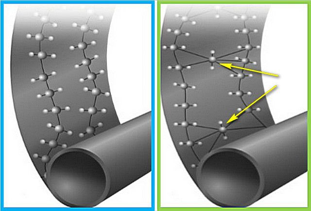
The more such binding "bridges", that is, the higher the degree of cross-linking of polyethylene, measured as a percentage, the more stable and better the material is.
There is one more remarkable property of cross-linked polyethylene - it is a kind of "memory effect". If the product changes its shape or configuration under the influence of any external loads, then when the conditions are normalized, it will tend to the initial position specified for it. For the manufacture of pipes, this becomes generally an invaluable advantage.
There is a generally accepted letter designation by which you can immediately determine that the product is made of cross-linked polyethylene - PEX. But usually these letters are followed by another one - this is a symbol that indicates the technology of creating cross-links in the molecular structure of the material. The operating characteristics of the polymer depend quite strongly on the method used, so it is worth dwelling on this nuance.
- PE-Xa - intermolecular cross-linking of polyethylene takes place under the influence of a chemical reagent - peroxide. Of all the technologies adopted to date, it is this one that gives the maximum degree of crosslinking - it reaches 85%. At the same time, the initial polymer in no way loses its qualities, but its strength and stability sharply increase, a particularly pronounced "memory effect" is noted.
The technology is quite complex and costly, but gives the best results at the end. It is also important that the crosslinking process lends itself to complete control, that is, a polymer with strictly specified parameters is obtained at the output.
- PE-Xb - cross-linking occurs using silanol technology, due to the so-called "grafting" of the active silane molecule and treatment with water vapor. I must say that such a technology was originally conceived as a cheaper replacement for PE-Xa. However, it cannot be said that the stated goal was fully achieved.
Cross-linked PE-Xb-polyethylene is inferior to plasticity, that is, it will be much more difficult to bend pipes along a small radius. The overall degree of crosslinking rarely exceeds 65%. The disadvantage is that the technological process is difficult to control, and at the output, products of different batches may differ in their parameters. Moreover, the stitching process, in fact, does not stop in finished products either - it simply goes into a sluggish phase. It turns out. That over time, the same pipes can become stiffer, sit down. In some countries, such polyethylene is prohibited for use in heating networks for this very reason - the connections on the fittings are not the most reliable, therefore they require regular tightening. Well, in reinforced-plastic pipes based on PE-Xb, the stratification of the general structure of the walls has been repeatedly noted.
- PE-Xc is cross-linked polyethylene, in which cross-links arise due to directional radiation of electrons. The production of this polymer is quite simple in terms of technology and inexpensive, but the material itself is significantly inferior to PE-Xa polyethylene.
It, of course, finds its application, for example, it goes to the manufacture of low-price metal-plastic pipes. They are quite applicable for water supply networks, but they can be used in a heated floor circuit with very great convention.
- PE-Xd - according to this technology, cross-links were formed due to the processing of raw materials with special nitrogenous substances. Currently, this method has completely lost the competition to others, and is actually not used, and pipes with such an index are not found.
Quality XLPE pipes are widely used in underfloor heating systems. Moreover, some of their types are designed exclusively for such functions.
- Metal-plastic pipes are in great demand among craftsmen, which combine the inner and outer layers of their cross-linked polyethylene and an inner continuous aluminum layer. The accepted designation for such pipes is PEX-Al-PEX.

1 - PEX inner layer
2 - outer layer PEX.
3 - a continuous layer of butt-welded aluminum foil.
4 - adhesive layers (adhesive), ensuring the integrity of the wall structure.
Such pipes have quite decent performance characteristics, since they combine the advantages of polymer and metal. They lend themselves well to bending (subject to special technological rules), stably hold the given contour configuration, and have a sufficiently high heat transfer.
But if we are talking about the contours of a warm floor, then the parameters of the polymer itself used to make the pipe come to the fore - this should be paid special attention to. The fact is that externally, metal-plastic pipes are very similar, and sometimes unscrupulous sellers tend not to tell the buyer about the intricacies, presenting their product as universal, suitable for any operating conditions.
As already mentioned, preference should be given to pipes in which the inner layer (or better, both polymer layers) are made of cross-linked PE-Xa polyethylene. They, of course, will not be cheap, but it's worth it.
The building materials market is literally teeming with fakes for branded products, and the risk of purchasing a low-quality pipe is quite large. Therefore, all your indecision must be "left at home" - be sure to ask sellers to have documents confirming the originality of the product and its compliance with standards.
You can find metal-plastic pipes in which the outer layer is made of PE-Xc or even generally from ordinary high-pressure polyethylene - PE-HD. They practically do not differ externally, but it is not worth using them in floor heating systems. Any experienced plumber can tell you how many breakthroughs in metal-plastic he has encountered in his practice. Over time, the unstable outer layer begins to "tan", crack, especially in the places of turns or bends of the hinges, and can easily crack. A thin inner layer and an aluminum layer will not be able to withstand the pressure from the inside in such circumstances.
In addition, gradual stratification of the pipe body is not excluded, since the materials still have different linear tension coefficients with increasing temperature. Therefore, despite the mass of real and apparent advantages, it is still worth abandoning the use of this type of pipes in the circuit under the screed. For these purposes, single-layer made of cross-linked polyethylene PE-Xa or PE-Xb are more suitable.

Such pipes are sold in large bays. They are very convenient for laying out even the most complex contours, and, subject to the fastening technology, they keep their shape perfectly. The plasticity of the material allows you to lay the contours with the smallest pitch between the turns - about 100 mm.
It is even better if it is possible to purchase such pipes, supplemented with a special barrier against oxygen diffusion. Penetration of active oxygen into the coolant from the outside causes and activates corrosion processes in metal parts and units of the heating system, and boiler heat exchangers are especially susceptible to such aging. To prevent such a process, special barriers against oxygen diffusion were developed.

1 - inner layer PE-Xa or PE-Xb
2 - EVON oxygen barrier.
3 - connecting layers.
4 - outer layer, respectively, also - PE-Xa or PE-Xb
By itself, this barrier is usually a layer of a special organic compound, polyvinyl alcohol. It is characteristic that all components of such a structure have equal characteristics of thermal expansion, therefore, even with significant thermal drops, no separation of the walls is threatened.
To all that has been said, it should be added that manufacturers of such pipes made of cross-linked polyethylene necessarily complete their products with convenient connecting elements that will simplify the connection of the underfloor heating circuits to the collectors.

In order to make it easier to choose a pipe, and it is more difficult for an unscrupulous seller to mislead the buyer, you can try to understand the marking system. It can be considered by example - although different manufacturers may have peculiarities in this matter, the general principle still remains.
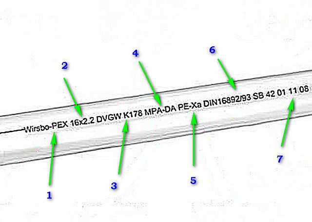
1 - usually the first position indicates the trade mark and the specific assortment type of pipe.
2 - data on the outer diameter of the pipe and the total thickness of its wall.
3 - codes indicating compliance with accepted international standards for permissible pipe applications. The indicator indicated in this example indicates that the pipe is suitable for pumping drinking water.
4 - the control technology used to assess the quality of the product.
5 - the polyethylene crosslinking technology discussed in the article above.
6 - confirmation of the pipe's compliance with the established standards DIN 16892/16893. These standards dictate the maximum values \u200b\u200bfor temperature and pressure of the pumped liquid. On some models of pipes, it is practiced to apply these indicators to the marking. For example, it might look like this:
« DIN 16892PB 14/60 °CPB 11/70 °CPB 8/90 °C ",
which will mean max 14 bar at t \u003d 60 ° C, 11 bar at t \u003d 70 ° C and 8 bar at t \u003d 60 ° C.
These indicators can be indicated in tabular form, attached to the batch of pipes technical documentation... In addition, the maximum service life can be given for different modes. For example:
7 - parameters of the batch of material - information about the date and time of release, the number of the production line, etc.
In addition to this information, the pipes are also marked along their length - this greatly facilitates both the control of the acquisition of the required amount and the laying of the contours itself.
Pipes based on polyethylene of high temperature resistance (PE-RT)
Attempts to modify polyethylene to the maximum have led to the creation of a fundamentally new material, designated by the abbreviation PE-RT, from the English name, literally meaning polyethylene with increased heat resistance. Now the second generation of this polymer is used in production.
Its main difference is that the material does not require additional technological stages of cross-linking - its molecular structure with numerous and branched bonds is already generally far from linear. Moreover, this quality is inherent in the initial material - the conglomerate supplied to the extrusion line is already fully a polymer with a stable molecular lattice. Interestingly, the loss of properties is not observed even during recycling.

Such polyethylene shows much better results in terms of resistance to high temperatures and pressure. Its service life can be calculated in tens of years. The unique molecular structure keeps the material thermoplastic, meaning it can be welded or soldered. This allows, in some cases, to carry out repair and restoration work without dismantling a fragment that has become unusable and without using fittings, which is completely impossible, for example, with PEX - there the damaged section will have to be removed.
Pipes made of PE-RT are not afraid of negative temperatures - they have the potential to withstand several cycles of complete freezing and thawing without breaking through the walls and without any loss of their performance.
Pipes “behave” perfectly in the contours of the warm floor, are distinguished by their noiselessness even with a strong pressure of the pumped heat carrier.
By analogy with cross-linked polyethylene, PE-RT is also used in the production of both pure polymer pipes (with or without an anti-diffusion layer) and metal-plastic pipes in various combinations. Since the main load falls on the base inner layer, it is it that is made of heat-resistant polyethylene PE-RT, and the outer protective layer can also be made of cross-linked PEX or even PE-HD. But in the highest quality pipes, both the outer and inner layers are made of PE-RT. So when choosing, you should pay special attention to the formula indicated in the labeling.

Probably, we can say with good reason that it is the PE-RT pipes that will be the choice that fully meets all the previously listed requirements for the "warm floor" contours and does not go beyond the reasonable in terms of the cost of purchasing material and components.
Prices for PE-RT pipes
pE-RT pipes
How many pipes are required for a "warm floor"?
It is very difficult to answer this question unequivocally. It all depends on the step of laying the contours, and it, in turn, is directly related to the tasks that are assigned to the floor heating system and the characteristics of a particular room.
To determine this issue, it will be necessary to carry out heat engineering calculations for each of the premises where the installation of a "warm floor" is planned. In fact, it is necessary to calculate the heat loss of the room, which must be compensated for by such a heating system. In any case, a "warm floor" will only make sense if measures are taken to maximize the thermal insulation of the room. Practice has proven that if the heat loss is more than 80 ÷ 100 W / m², then the arrangement of such heating systems for housing will turn into absolutely unjustified losses of effort, money and time.
It is also important whether the “warm floor” will be the main source of heat energy, or it is planned only as a means of increasing comfort in certain rooms or even in some limited areas, that is, it will work in “tandem” with radiators.
Typically, the laying spacing ranges from 100 to 300 mm. It is impractical to reduce it, and often it is simply impossible, since this will not allow the permissible bending radius of the pipe. If the installation step is too large, the heat will be unevenly distributed, and there will be a “zebra effect” - clearly noticeable stripes with different levels of heating of the floor surface.
In areas requiring increased heating, the laying of the circuit can be locally compacted, and in areas a step vacuum is permissible, but still within the specified limits.

Thermal calculations, taking into account all the features of the premises, is a rather complicated procedure that requires certain knowledge. It deserves a separate detailed publication, and will not be considered within the framework of this article. The best way out is to entrust this matter to specialists who will help you determine the outline drawing and the step of its laying, draw up a diagram. And only then it will be possible to calculate the required amount of pipes for the "warm floor"
You can use the following calculation formula:
l = k × Syh /hyh
l - the length of the contour in a certain area.
Sych - land area.
hyh - the step of laying pipes on the site.
k - coefficient taking into account pipeline bends.
Coefficient k also depends on the laying step and is in the range of 1.1 ÷ 1.3.
To make it easier for the reader, below is a handy calculator, which already contains all the relationships. You can calculate the lengths of pipes for each section with a certain laying step, then sum them up, and do not forget to add the distance to the tie-in point (collector, plus leave about 500 mm at each end for connection.
In the modern world, everyone already knows and understands what a warm floor is, and you definitely won’t surprise anyone. In almost every private house where there is an autonomous heating system, the owners are going to install a water floor on their own - if this is provided for by the project. Of course, a water floor system can be installed in an apartment, but this is said with a very big stretch, since not every management company will allow you to reconstruct the central heating system of a residential building for your "whims", and installation of an additional autonomous boiler for such heating systems is more likely everything will turn out to be very expensive.
The pipe for a warm floor, which runs throughout the room of your house, may be different, and in order to understand which pipe to choose exactly for your home, and calculate its quantity, you need to analyze this topic in more detail. So let's figure it out.
System installation methods
There are several ways to install the "warm floor" system - floor and concrete. In the second case, the warm floor will have a screed, in the first - as the name implies, the flooring is made of a completely different material (polystyrene or wood). For the first method of installing the underfloor heating system, "wet processes" are unusual, and therefore all floor installation work is carried out much faster.


Nevertheless, installation of a warm floor is not for everyone - there is an impossible task - of course, if you have enough funds and capabilities, then it is better to hire professionals. And for those who save their money, or have a great desire to assemble a system of warm water floors themselves, they can do everything themselves, while saving a significant amount of financial resources.
Installation system "Concrete"
At present, the "Concrete" installation system is very popular due to its simplicity. The pipe for underfloor heating, the price of which depends on the material from which it is made, is laid along a common contour. Such a pipe for a warm floor is poured with a concrete screed without special heat energy separators.

The entire area of \u200b\u200bthe future heated room must be divided into small areas. The number of such areas depends on the size and geometry of the room (it is imperative to maintain the aspect ratio of the contours of 2: 1). This is closely related to the further expansion of the concrete screed when the underfloor heating system is turned on - under the great influence of a decrease / increase in temperature in pipes for a warm floor, the screed will deform, and this should be avoided in order to prevent cracking of the floor covering.
The sub-floor must be covered with a layer of thermal insulation. To do this, it is necessary to clean the base of the floor, then lay the heat-insulating material - so that there is no heat loss at the base of the floor.
If you use the "correct" material for thermal insulation and correctly lay it, as well as make an accurate calculation of the pipe for a warm water floor, then the heating of the water floor itself will go exclusively upwards.

It is recommended to use polystyrene as thermal insulation - the main thing is that the thermal insulation layer has a density above 35 kg / m3 and a thickness of up to 150 mm. The thickness is calculated by the nature of the room - how saturated the heating should be. And on top of the insulation layer, it is necessary to lay a simple polyethylene film necessary for waterproofing. Then, around the entire perimeter of the room and between the sections, it is necessary to place a damper tape, which is designed to compensate for the thermal expansion of the concrete screed.
Next, you need to reinforce the insulation layer and then lay pipes for the underfloor heating along the contour, the price of which varies depending on the material. Typical reinforcement - mesh with cell dimensions 150x150 and bar section up to 5 mm. If it is necessary to reinforce the concrete screed, as they say, on the conscience, then you can lay another layer of mesh - after the heating pipe has been laid under the warm floor.

Installing hot water heating yourself is quite simple. Having made a preliminary calculation of the length of the underfloor heating pipe according to the scheme, the project itself is calculated directly. The distance between the underfloor heating pipes should be within 30 cm, and depending on the geometry and location of the sections, the installation scheme itself is designed: with a spiral with an offset center, a spiral, a snake or a double snake. The heating element - the pipeline - must be fastened with clamps to the reinforcement mesh, and a corrugated pipeline must be installed in the expansion joints on the pipeline, protecting it from possible damage.

Laying underfloor heating pipes near the outer walls implies reducing the pitch of the tubes - in order to avoid temperature differences, since heat losses near the outer walls will be much higher. And the length of the underfloor heating pipes should be approximately 70 meters.
The maximum length of the underfloor heating pipe is 90 meters, otherwise there will be very significant heat losses at the end of one or several circuits and a drop in the operating pressure of the coolant in the system.
The number of pipes for a warm floor is calculated as follows - for 1 m 2 of surface, on average, 5 running meters are needed. pipeline (provided that the distance between the pipes is 20 cm). Pressure testing is the final stage of the installation of the pipeline in the underfloor heating system - it can be used to identify mechanical damage to the pipeline that exists at this stage. Pressure testing must be carried out under operating pressure for at least 24 hours.

Then, after pressure testing (all work takes place under pressure), concrete solution is poured. Layer thickness - up to 70 mm, as a fill, you can use a special mixture for such floors or sand concrete M300.

As for fine finishing, then produce it only after the screed solution has completely solidified. As finishing materials it is necessary to select exactly those that have excellent thermal conductivity (for example, linoleum, ceramic tile or laminate).
Installation system "Polystyrene"
Such a system is considered easy to install, since it involves the installation of polystyrene plates on special grooves available for aluminum plates. A red pipe for a warm floor (supply pipe (blue - return)) is snapped into the plates, on which the floor covering itself is placed. The absence of a concrete screed is an advantage for homeowners - you will not have to waste time waiting for the complete hardening of the solution, but immediately apply the system for its intended purpose.

Calculation of a warm water floor
For the safe installation of a warm floor, it is necessary to prepare in advance all the necessary materials, plan the order of work. At the preliminary stage, the most difficult questions will be: "Consumption of pipes for underfloor heating", as well as the purchase of the necessary components. Let's see what we need to calculate the diameter of the underfloor heating pipe, and also see which ones today best pipes for a warm floor.
So, firstly, if the installation of dimensional furniture or equipment is planned in the room, then it is impossible to install the pipe under it. Accordingly, the area will shrink. In addition, it is imperative to step back from the wall at least 200 mm - this must be taken into account when calculating the total area of \u200b\u200bthe warm floor.
Secondly, the question of which pipes for underfloor heating are more or less suitable for you needs to be solved with a specialist who will definitely recommend the necessary pipe for your room, and may also advise where to buy it, a pipe for underfloor heating can be completely different ... It can be metal-plastic, copper, polypropylene, etc. The most important thing when calculating the number of pipes is the laying step. The more you need the room temperature, the less you need to take this step.
It covers such topics as: the maximum length of the water floor heating circuit, the location of the pipes, optimal calculations, as well as the number of circuits with one pump and whether two are needed the same.
The popular wisdom calls for measuring seven times. And you can't argue with that.
In practice, it is not easy to embody what has been repeatedly scrolled in your head.
In this article we will talk about the work associated with the communications of a warm water floor, in particular, we will pay attention to the length of its contour.
If we plan to install a water-heated floor, the length of the contour is one of the first questions that need to be dealt with.
Pipe arrangement
The underfloor heating system includes a considerable list of elements. We are interested in pipes. It is their length that defines the concept of "maximum length of a warm water floor." It is necessary to lay them taking into account the characteristics of the room.
Based on this, we get four options, known as:
- snake;
- double snake;
- corner snake;
- snail.
If you do correct styling, then each of the listed types will be effective for space heating. The length of the pipe and the volume of water can be (and most likely will be). This will determine the maximum length of the water floor heating circuit for a particular room.
Main calculations: water volume and pipeline length
There are no tricks here, on the contrary - everything is very simple. For example, we chose the snake option. We will use a number of indicators, among which is the length of the contour of a water-heated floor. Another parameter is diameter. Pipes with a diameter of 2 cm are predominantly used.
We also take into account the distance from the pipes to the wall. Here it is recommended to fit within the range of 20-30 cm, but it is better to place the pipes clearly at a distance of 20 cm.
The distance between the pipes themselves is 30 cm.The width of the pipe itself is 3 cm.In practice, we get a distance between them of 27 cm.
Now let's move on to the area of \u200b\u200bthe room.
This indicator will be decisive for such a parameter of a warm water floor as the length of the contour:
- Let's say our room is 5 m long and 4 m wide.
- Laying the pipeline of our system always starts from the smaller side, that is, from the width.
- To create the base of the pipeline, take 15 pipes.
- A gap of 10 cm remains near the walls, which then increases on each side by 5 cm.
- The section between the pipeline and the collector is 40 cm. This distance exceeds those 20 cm from the wall, which we talked about above, since in this section you will have to install a water drainage channel.
Our indicators now make it possible to calculate the length of the pipeline: 15x3.4 \u003d 51 m. The entire contour will take 56 m, since we should also take into account the length of the so-called. collector section, which is 5 m.
The length of the pipes of the entire system must fit into the permissible range - 40-100 m.
amount
One of following questions: what is the maximum length of the water floor heating circuit? What to do if the room requires, for example, 130 or 140-150 m of pipe? The way out is very simple: it will be necessary to make more than one contour.
The main thing in the operation of a water-heated floor system is efficiency. If, according to calculations, we need 160 m of pipe, then we make two circuits of 80 m each.After all, the optimal length of the water floor heating circuit should not exceed this indicator. This is due to the ability of the equipment to create the required pressure and circulation in the system.
It is not necessary to make the two pipelines absolutely equal, but it is also not desirable for the difference to be noticeable. Experts believe that the difference may well reach 15 m.
Maximum length of the water floor heating circuit
To determine this parameter, we must take into account:

The listed parameters are determined, first of all, by the diameter of the pipes used for the warm water floor, the volume of the coolant (per unit time).
In the installation of a warm floor, there is a concept - the effect of the so-called. locked hinge. This is a situation where circulation through the loop will be impossible, regardless of the pump power. This effect is inherent in a situation of pressure loss, calculated at 0.2 bar (20 kPA).
In order not to confuse you with long calculations, we will write several recommendations, proven by practice:
- A maximum circuit of 100 m is used for pipes with a diameter of 16 mm made of metal-plastic or polyethylene. Perfect option - 80 m
- 120 m contour - limit for 18 mm XLPE pipe. However, it is better to limit yourself to a range of 80-100m
- With a 20 mm plastic pipe, you can make a contour of 120-125 m
Thus, the maximum pipe length for a warm water floor depends on a number of parameters, the main of which is the pipe diameter and material.
Are two identical ones needed and possible?
Naturally, the ideal situation will look when the loops are of the same length. In this case, you will not need any settings, search for a balance. But that's in to a greater extent in theory. If you look at practice, it turns out that it is not even advisable to achieve such an equilibrium in a warm water floor.
The fact is that it is often necessary to install a warm floor on an object consisting of several rooms. One of them is emphatically small, for example, a bathroom. Its area is 4-5 m2. In this case, a reasonable question arises - is it worth adjusting the entire site for a bathroom, splitting it into tiny areas?
Since this is not advisable, we come to another question: how not to lose on pressure. And for this, such elements as balancing fittings were created, the use of which consists in equalizing pressure losses along the contours.
Again, calculations can be used. But they are complex. From the practice of carrying out work on the installation of a warm water floor, we can safely say that the spread in the size of the contours is possible within 30-40%. In this case, we have every chance to get the maximum effect from the operation of a warm water floor.
Despite the considerable amount of materials on how to make a water floor yourself, it is better to contact a specialist. Only foremen can assess the working area and, if necessary, “manipulate” the pipe diameter, “cut” the area and combine the laying step when it comes to large areas.
Quantity with one pump
Another frequently asked question: how many circuits can operate on one mixing unit and one pump?
The question, in fact, needs to be specified. For example, to the level - how many loops can be connected to the collector? In this case, we take into account the diameter of the collector, the volume of the coolant passing through the node per unit of time (the calculation is in m3 per hour).
 We need to look at the data sheet of the node, where the maximum throughput factor is indicated. If we carry out the calculations, then we will get the maximum indicator, but we cannot count on it.
One way or another, the maximum number of circuit connections is indicated on the device - as a rule, 12. Although, according to calculations, we can get both 15 and 17.
The maximum number of outputs in the collector does not exceed 12. However, there are exceptions.
We saw that installing a warm water floor is very troublesome. Especially in the part where it comes to the length of the contour. Therefore, it is better to turn to specialists so as not to redo the not entirely successful styling later, which will not bring the efficiency that you expected.