A do-it-yourself soldering iron stand is a sign of a good work style. How to make a soldering iron stand Homemade soldering iron stands
A little backstory. Long wanted do normal stand for soldering iron but didn't know where to start. Recently, I came across a lid (I don’t remember exactly why), which had been in the box for a long time.

She gave me the idea for the design.
To make the stand I used:
- "unknown" cover (stand);
- plywood;
- wooden bead;
- self-tapping screws;
- nails;
Description of work
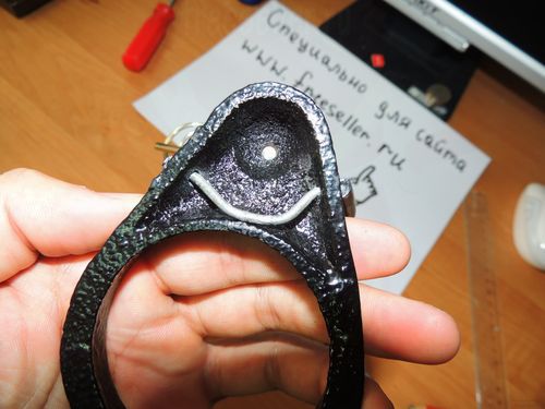
To begin with, I removed everything superfluous from the lid.

 On the sides were left "tongues" that will play the role of fasteners.


Next, 3 planks were cut out of plywood. Since the bottom of the lid is not even, a substrate was sawn out for convenient attachment to the base. 
 From three sawn boards:
- the largest is the base of the entire structure;
- the other two are the same. A soldering iron mount will be installed on one, in the other I made holes into which jars of fluxes for soldering will be placed. Also in the substrate, I made holes in the shape of the bottom of the lid.

I drilled holes in the tongues. After that, I screwed two identical planks onto the screws.

In order to prevent the flux jars from falling through, a small plank was cut out of plywood, two small glazing beads were sawn to the plank.

I nailed this plank to the base with carnations, placing sawn glazing beads under it.

A partition was cut out of tin into a lid. From the tin that was cut off from the lid, I bent the stand on which the soldering iron will lie. The partition was screwed to the base with screws through the holes in the cover. The stand was screwed to the board without holes.


 Under the plank on which the soldering iron will lie down, I sawed out 2 glazing beads and nailed them to the studs.

I placed a sponge in the part of the lid with a partition. Cellulose sponge for washing dishes. Sponges that are sold specifically for cleaning soldering tips are no different from cellulose sponges for washing dishes, only in size and price. Sponges for dishes are much larger in size, and cheaper in price. This sponge was bought at a hardware store for 30 rubles.
The lower part was removed from the sponge. I also cut it to fit the lid.

Initially, I wanted to make something simple, namely a soldering iron holder with a temperature controller, since the soldering iron overheated, but once I started, I could not stop. He made all the necessary adaptations gradually, and therefore every time new ideas arose.
So, we need:
Material:
Chipboard board;
Bolts of different diameters;
Screws, self-tapping screws;
Nut-Lamb (10 pcs.);
Crocodiles (3 pcs.);
Door hinge (1 pc.);
Unnecessary flashlight;
3 motors (2 from the printer, 1 weaker from the typewriter);
4 LEDs (3.5 volts);
5 switches;
Collet;
Small sharpening nozzle (from the set for the engraver);
Helium paste (adapter for nozzle);
wires;
soldering iron;
3 corrugated tubes (from a gas lighter);
Cigarette case;
Tin coil;
Socket;
Door knob;
4 meters of cable;
2 power supplies (from a 5-volt phone charger and a 9-volt router);
Self-adhesive film, edge;
Black paint;
Tool:
soldering iron;
Glue gun;
Chisel;
Metal scissors.
So, let's begin
We take a chipboard board, mark it out and cut it out in an L-shape, the dimensions are attached.
At a specially selected place, we mark and cut out holes for push-button switches (4 pcs.).

In order to conveniently place our devices, and they could be adjusted, double L-shaped levers were made, cut out of tin, for each individually.
The cheapest soldering iron stand was bought.

And now we will refine it!
It was decided to make 2 crocodile holders, for this we drill 2 holes on the sides, take a steel wire, and push it through the bottom.
Next, we bring the ends to the top, level them flush with each other, bend them so that they look solid? we take 2 corrugated tubes taken from a gas lighter, put it on a wire, and then we attach a crocodile on each side, and also drill a hole in the saucer in order to screw it tightly to the surface of the board, as a result we get.

We make the third vertical crocodile, bend it in this way.

It is attached to the bottom of the stand.

It was decided to make a mini drill, as well as a sharpener for small parts. For this, 2 unnecessary motors were taken from the printer.

A sharpening nozzle was attached to the motor, using an adapter from a helium pen. The motor itself was fixed to the found metal form, in such a way that it could stand upright.
In order to be able to work at night, we make lighting from an unnecessary flashlight, in my case of this type.

We remove the excess, and leave only the part with the LED.

In order for the lantern to move up and down, an adapter (cap) was taken, a through hole was drilled, a long bolt was inserted, holders were cut out, and everything was clamped with a wing nut, in this way.


Sometimes you have to work in hot weather, so I wanted to add such a nice little thing as a fan. We take the most common motor and make a case for it. The broken charger from nokia was optimally sized. We cut off the plug, take out the core and cut out a place for the motor.

The wires were soldered, assembled it looks like this.

In order to be able to solder small elements, we take a magnifying glass, remove the excess and make a backlight using 4 LEDs of 5 volts each, and fasten it with a glue gun.

We cut out two plates, bend them in the form of a slingshot, drill, and thread a long bolt, this is how it all looks.

We fix to the body of our mini drill, in this way.

In order for the stand to be used anywhere, add 4 meters of cable and the usual door handle, for its winding.

Drill 2 holes for the fork.
 |
|


We drill 4 holes for fastening, we make partitions.

We put together everything you need.

We make the main holder for the soldering iron, handle and tip.
Cut out 2 plates, bend, fasten to door hinge, and from below to the board itself.
The door hinge is needed so that when unwinding the cable, we can remove the soldering iron to the side, and it does not interfere with us.
|
|
|


Since the soldering iron overheated a lot, and it was almost impossible to solder, it was decided to make a temperature controller, after looking at the diagrams, etc., I decided that it would be easier to buy an inexpensive dimmer (dimmer) of this type.

Having disassembled it, and cut out a place for the board in the board, brought 2 wires to the bottom, left one half of the case, and drilled a hole in the middle for the regulator wheel.
 |
|

Attached to board with 2 screws.

I'll post the wiring diagram below.
In order to be able to work in one place, as well as for convenience, we put an outlet, which makes it possible to connect a glue gun, phone charger, etc. things.

We make such a delivery, where you can put a jar of flux, or something else. Cut out of an old watch case.

When all the fixtures are ready and painted black, glue the self-adhesive film onto the surface of the board. A light color was chosen, since all the details are clearly visible on such a surface, the side faces are pasted over with an edge.
The main tool of a home radio amateur is a soldering iron. Unlike other appliances, it cannot simply be placed on a table (workbench) during operation. Why? Right! He is hot. Therefore, you will need a special stand.
There are many different devices on sale, from a simple holder to a whole complex called a soldering station.
In most cases, a soldering iron is needed to perform urgent repair work. If you are not a professional "homemade" - the tool usually gathers dust in a box on the balcony, appearing once or twice a year. In such cases, many use the first object that comes across as a stand.
However, if you put in quite a bit of effort, a hand-made soldering iron stand will look no worse than a factory one. Especially if you regularly make electrical circuits.
Required minimum for stand
- Stable foundation. Made of a material that conducts heat poorly, or equipped with legs
- Soldering iron supports
- Container for rosin (flux).
Additional options"
- Tinning area
- Solder container
- Sting Cleaner
- power regulator (can be of two types: smooth adjustment, or stepwise limitation for the time of a break in work).
Flipping through old magazines
In old Radio magazines, you can find drawings on how to make a stand with an economical load switch.

- As a basis (1), a board with a selected middle is used, or a U-shaped structure made of a strip of plywood and two bars along the long edges
- Under the surface there is a relay contact group for 220 volts (2,4,5) with large current collection areas. The wiring diagram transfers power either directly or through a diode. The radio element "cuts off" the half-cycle of the alternating voltage of 220 volts, reducing it to a value of 110
- Through the rod (6), the spring-loaded (7) button (8) presses the contacts when the soldering iron lies on the stand. Electricity is spent half as much, while the soldering iron almost instantly warms up to full power. The rod is attached to the console (9)
- The tool itself is located on the brackets (3) and (10)
- At the rear is a soldering iron socket connected to the relay output contacts. The power cable is connected to the input
- Between the racks, they usually nailed a tin of shoe cream or petroleum jelly to store rosin
The design is simple, but convenient and effective. If you don’t want troubles with contacts, we make a simple functional stand. Again, from the experience of Soviet radio amateurs.
- We take a piece of plywood or chipboard from old furniture. Cut out a rectangle
- From a piece of galvanized steel, we cut out a workpiece the size of a palm, for a dovetail support
- We bend the plate, we get the finished element. By the way - such a detail can already be used as a primitive stand
- To hold the solder spool, we screw a steel pin into the base
- The third element is the universal trough. Can be used as a tin table or rosin storage. This completes the design.
Third hand - work comfortably
When soldering by weight, it becomes necessary to hold two parts and a soldering iron at the same time. This is where the term "third hand" comes from. In the next review, a homemade stand with such a device. The materials and tools that will be needed for manufacturing are shown in the photo:
Factory-made details - crocodile clips, decorative candles (or rather cups from them), a flexible leg from an old mini lamp and a spring holder. The donor was a Chinese stand for a soldering iron with a magnifying glass.

Although you can make such a spiral with your own hands by winding a steel wire around a pipe or a screwdriver handle. The rest of the blanks are also replaceable, homemade is shareware, from improvised trash. With a drywall crown, we mill recesses for cups from candles. Two niches for rosin and solder, and one niche for cleaning cloth.
IN comfortable spot(not in the center) we mount the spiral holder for the soldering iron. Practice has shown that such a scheme is more convenient than the classic horn stand for a soldering iron. The appliance is inserted in one motion, without fear that it will fall on the table.
We install aluminum cups in prepared niches, cut off the edges flush with the board. The use of thin-walled containers justifies itself when working with low-power soldering irons. The less metal, the lower the heat capacity. The thick walls of the solder cup can cool the small tip of the soldering iron when touched. A thin aluminum foil surrounded by wood, on the contrary, retains heat.
We crimp the "crocodiles" on a flexible rod, and fix the "third hand" on the stand. There are designs with a magnifying glass. Work experience shows that the stand for the soldering iron, on which the clamps and magnifier are installed, is inconvenient to use.
Best Options
- the magnifying glass is combined with the "third hand", the soldering iron is separate
- "third hand" on a stand with a soldering iron, a magnifying glass on a separate pedestal (our version).
The only thing missing is the ability to change temperature conditions work. This is especially true when mounting LEDs.
Stand and power regulator for soldering iron
The simplest and relatively affordable option, this is the purchase of a Chinese kit soldering station. You will assemble such a KIT yourself, so we will classify it as homemade.

It can be assembled in a stand case or as a separate device. The convenience of this design is undeniable, but we consider the least expensive options. There is a 220 volt soldering iron in almost every home, it remains to assemble a power regulator.
Important! Dimers for incandescent lamps can be used, taking into account the power of the soldering iron.
But again, you have to buy them. Consider a simple circuit homemade regulator power up to 200 watts.
You can use an autotransformer, but this is a bulky device with low efficiency. Let's leave such "devices" for the museum of radio engineering. Our triac circuit is miniature and economical.

You will need the following items
- variable resistor (voltage regulator) R1 up to 500 Ohm
- the second part of the divider is a fixed resistor R2 with a nominal value of 4.7 kOhm
- C1 - AC capacitor 0.1 uF
- VD1 - diode type 1N4148
- LED element VD-2 for power indication
- dinistor series DB3 (in the diagram - VD3)
- the main element is the BTA06-600 triac, designated as VD4.
The circuit provides continuous operation with a load of 200-300 watts. Short-term load up to 500 W is allowed.
Drawing of self-etching circuit board:

We carefully assemble the board, carefully soldering the legs of the parts. If the contact is broken, uncontrolled voltage surges can be obtained at the output.
The circuit is compact, it can easily fit on a soldering iron stand. At power up to 100 W, triac cooling is not required. Bree greater load - a small radiator is attached to the case.

After reviewing the material, you yourself will decide which stand to make. Or watch a visual video tutorial on making a stand with your own hands.
Do-it-yourself soldering iron stand - a sign good style works Link to main publication
obinstrumente.ru
DIY stand for a soldering iron
Many offline and online stores sell good and quite convenient stands for soldering irons, and inexpensively. But if you wish, you can make them yourself.
It will turn out cheaper, plus you can adapt the stand for own needs.
There are a lot of manufacturing ideas, so we decided not to limit ourselves to one, but to make a selection of the most interesting, in our opinion, home-made soldering iron stands made by ourselves.

Wire stand for soldering iron.
Let's start with the most budgetary, simple and common option. In it, the soldering iron mount is made of thick metal wire in the form of a conical spring and is attached to a wooden or other base.
Instead of wire, you can use thin metal clothes hangers, which are in almost every home.


Such a stand can be made more convenient if you install additional buns on it, for example, a metal sponge for cleaning the soldering iron, a box for tin and rosin, or a soldering holder.


You can also make another homemade soldering iron stand from wire, a little less convenient (although this is a matter of taste) and just as easy to manufacture.


Stand for a soldering iron from fuses.
Another option is very easy to manufacture and cost-free stand. The base is made of a wooden block or textolite, fuse sponges of the desired size are attached to it from above.


Mobile stand.
Homemade mobile stand for soldering iron, made of sheet metal obtained from a burnt power supply from a computer. The stand is intended primarily for people who often solder outside the home. It is quite comfortable and functional, while it easily fits in a bag or even in a jacket pocket.

Having such a stand, you do not have to carry separately tin, rosin and a clamp for soldering small parts. Where and what is stored is well shown in the video, we recommend that you watch it.
Well, with the instructions for manufacturing, you can find here.
Sophisticated stands for a soldering iron with your own hands.
Sophisticated multifunctional coasters are a matter of taste. Some people really like them, others prefer simple designs which we showed above. In any case, complex coasters deserve attention, as they are made cool.
We will show only a few of them, the most interesting in our opinion.
The first stand has everything you need for comfortable work, namely a place for tin and rosin, a clamp for soldering small parts, a sponge for cleaning the tip, a built-in regulator, and, of course, fasteners for quick but reliable fixation of the soldering iron.

See the manufacturing process here.
Well, at least two more interesting ideas in video format.
The simplest stand.
If you urgently need a stand for a soldering iron, then making something complicated is not best idea, as haste always leads to hack work. It is better to temporarily make a simple design, and then change it to something more worthy.
Most the best option, which is done in just a couple of minutes - this is wooden beam ok with four long screws. The soldering iron lies well on it, it is easily pulled out, but at the same time it does not fall out.

www.samodelki.org
DIY soldering iron stand
In contact with
 Good day to all lovers of homemade products. every radio amateur or just a beginner in this business knows how to work with a soldering iron, and for him convenient use stand is required. It is in this article that I will talk about how to make a homemade budget soldering iron stand.
 In order to assemble our stand you will need:
* A chipboard sheet, 18 mm thick, can be thicker, but it seems to me the thickness is the most optimal. * 4 self-tapping screws 20 mm and 4 smaller bolts. * Coarse-grained sandpaper. * A couple of rubber stoppers from chemical test tubes. * Hacksaw. screwdriver or screwdriver.* Thin screwdriver, an awl will also work.* Pliers.* Iron plate.* metal mount from the antenna. * A tin from an old receiver that closes the board. * A spring from a fountain pen. * The soldering iron itself for testing. The first step is to grind the already sawn chipboard sheet. We grind carefully, and give the edges a rounded look. We bring the blank for the stand to this type. The photo shows which workpiece was before grinding, and which after. 


 Thinking that many store-bought coasters are so simple that they don't have legs, I decided to make rubber feet for my coaster.
  We cut rubber stoppers taken from chemical test tubes with a hacksaw, make their thickness the same with sandpaper, if it was not possible to saw off exactly.
 After that, we screw a 20 mm self-tapping screw into each leg.
  And in the pre-prepared hole we twist the leg with the screw.
  We fasten the first leg. Similarly, we fasten the second, third and fourth. We figured out the legs, now the stand will not go anywhere and will not scratch the table.


 The next thing I did was bend the iron plate into a hook shape, as shown in the photo.

 Using a screwdriver for small parts, I made a hole for two bolts that will hold this hook.
 We tighten the bolts, as we see the hook is holding well.

 We try on how the soldering iron will sit.
  With the help of pliers, bend one end of the hook, it should look something like this.
  So, the heating part of the soldering iron is not going anywhere now, so let's move on to the back of the soldering iron, or rather to the handle.
  There is also a notch where the soldering iron handle fits well.
 We fasten this mount with two screws.
 And now the soldering place, since the tin needs to be taken from somewhere, for convenience we will make it closer to the soldering iron tip. I punched a hole in the plate, which I took out of the radio receiver, and screwed a bolt into it, he firmly pressed it to the stand.


 From ballpoint pen, which had just ended, I removed the spring and decided to put it on our hook, first bent one end of it, then made a hole with a screwdriver in the board of the stand and launched this end of the spring there, and soldered it to the hook at the top.


 The stand is almost ready, the next thing I did was melt the tin at the place of soldering, now, if necessary, you can warm up this place and tin the wires there.
 The final stage was the decor, I glued the old nameplate from the electric razor to the stand.
  On this, a home-made stand for a soldering iron is ready, it is more convenient and comfortable to solder with it, and the rubber feet will not let it come off a slippery surface and will not scratch the table.
  All interesting and unusual ideas for new crafts. Become the author of the site, publish your own articles, descriptions of homemade products with payment for the text. Read more here.
In contact with
Rate homemade:
7 To write a comment, you must enter the site through the social. network (or register): Regular registration
Information
Visitors in the Guests group cannot leave comments on this post.
usamodelkina.ru
Do-it-yourself budget stand for a soldering iron.
 This article, I believe, will be, first of all, useful to those who are only taking their first steps in the world of electronics, but I do not exclude that there is something in it, and something for radio amateurs with extensive experience.
 And so I'll start with a brief background. Somehow, I went to our local radio market once again to buy components, and I didn’t see the soldering iron EPSN “Reksant” with a power of 25 watts there. He immediately attracted my attention. By itself, the idea arose to update my instrument. More than half a year of its operation has passed since the date of purchase and so far I have no complaints about it. Then the seller offered a stand for him. But I politely declined, citing lack of funds. Actually, it is a cast iron casting in the form of a stand. Of the pluses, this is massiveness and a relatively convenient position of the instrument on the table, there is a small tray of arbitrary shape (for which it is not clear). Of the minuses, too heavy (in my opinion), the raw surface of the sole easily scratches the table (can be successfully used instead of a rasp).
Previously, I came across very worthy coasters, but their cost was many times higher. I must say that this soldering iron is quite light. So light that the power cord always strives to drag it somewhere to the side. Actually the idea of \u200b\u200bmaking comfortable stand visited me several times, but then I still matured. First of all, I set myself the task, the device should be as cheap as possible, easy to manufacture and convenient, not take up much space on the table and be as functional as possible. I shoveled the Internet, having familiarized myself with what trade offers today in terms of models, forms and technical solutions. At the same time, I also looked for suitable schemes for adjusting the temperature of the soldering iron tip. Actually, for such a low-power soldering iron, adjusting the temperature of the tip is not particularly necessary. But in the future I'm going to buy more powerful soldering irons from this company. I started manufacturing, first of all, with the electronic part, since it would be necessary to dance with the dimensions of the case depending on its size. The circuit based on the K1182PM1 chip attracted attention. The diagram is taken from the datasheet. The microcircuit is intended mainly for controlling the voltage of incandescent lamps, although the range of its application is much wider.


True, the control scheme was somewhat modified for some reason and purpose. I encountered this microcircuit for the first time, and it’s hard to say how much, the circuit from the datasheet with triac control is correct. But in this version, the operation of the circuit did not suit me, and after some experiments it acquired the following form.

The triac was added to the circuit for greater reliability of the device, although, as they say, the microcircuit can confidently “pull” a load of up to 150 watts. Resistor R2 sets the required minimum temperature of the soldering tip. Resistor R3 sets the tip temperature in “standby” mode. Well, R4, R5 had to be paired with a nominal value of 2 × 20 Kom, turning them on in series. There just wasn't a potentiometer of a suitable design with the right rating. As practice has shown, the maximum resistance of the potentiometer should be 33 - 35 Kom. I drew the board in DipTrace 2.4. I have been using this program for many years, I started with version 1.4. The interface of this program is quite simple and convenient. I tried other tracers, but this one came to my liking closer. But here, as they say, the taste and color ... This time I decided to make a board according to the old method (drawing by hand), since its size is not large. Actually, I didn’t want to fool around with LUT or photoresist on a piece of fiberglass. The board is double-sided and uncomplicated, so drawing the tracks took about 20 minutes. To do this, I always have markers in stock and a homemade template made of transparent plastic with a “line” of holes.

I use SCHOLZ markers and am very happy with them. Once I bought a bunch of markers from different companies, and carried out an etching test on them, this one showed the best result. Edding and Centropen behave somewhat worse. Plus, it dries almost instantly. Because of this, they have to be stored in the refrigerator in an upright position with the feather down. The seller shared this secret with me.
Etching has recently been carried out in a solution of citric acid, hydrogen peroxide and common salt. This recipe, in my opinion, is slightly inferior in etching speed to ferric chloride and persulfates. But the most affordable, cheap and safe. It is still relatively safe, since it is undesirable to enter the body. There is a risk of copper citrate poisoning. True, there is a minus, the solution is disposable and cannot be stored for a long time. This is what the electronic part of the device looks like.

Correctly assembled circuit works without problems. Before using for the first time, in order to avoid electro-smoke and fireworks, it is advisable to check the correct installation. When setting up, it is better to use an incandescent lamp to visually control the operation of the device.
All elements of the device are under the influence of mains voltage, so all safety precautions must be observed. Pay special attention to the insulation of all electrical circuits.
When I figured out the electronic part, I took up the manufacture of the stand itself. The case for the electronic part was made of a square tube 60 × 60 mm in size and 2 mm thick in the wall. I soldered threaded bushings to the upper and lower parts of the case for attaching to the base and attaching the top cover and everything that is on it. I soldered with POS60 solder, used a mixture of a solution of zinc chloride and ammonium chloride (ammonia) as a flux. Soldering iron 100 watts and additionally to help a small gas burner to speed up the process.

After soldering with such a flux, be sure to rinse all soldered parts with water and detergent and dry everything well to avoid corrosion of parts in the future.
If you are very sorry for your health, then soldering with the use of active fluxes should be carried out in a ventilated room or in the open air.


As a “carriage”, I used a thin-walled pipe with an outer Ø 34 mm and a wall thickness of 1 mm. Ventilation holes are drilled along the pipe on four sides. At the bottom of the pipe, a tube is soldered for mounting on the axis. Also, a stop is attached to the pipe, which, through the pusher rod, presses on the limit switch when the soldering iron is installed in the “carriage”. The pipe itself is taken from the giblets of the shock absorber strut passenger car. Inside the pipe, he installed a conical spiral, which he twisted from galvanized wire Ø 3mm. On the end of the pipe I glued a piece of a bicycle chamber from the outside and from the inside with a “stocking”. Now the soldering iron is fixed tightly, but not tight without fear of being accidentally pulled out of the stand. The shelf for interchangeable tips is also made of a square pipe, cut out in the form of the letter “P” and soldered to the cover of the device. To it, the solder supply unit is attached. For marking on steel it is very convenient to use a solution blue vitriol. A solution is applied to the cleaned metal surface with a swab or brush, and after drying, you can start marking. There is no need to take deep risks. For high-quality marking of the centers of future holes, it is convenient to use a center punch with a lens, for example, like this.

I made the trays from an aluminum thin-walled pipe, but to save space I gave them a rectangular shape. I did it very simply, I counted the circumference into the required rectangular perimeter. Next, I cut a beech bar about 25 cm long and gave it a light wedge-shaped shape with roundings. With light blows of the hammer on the bar, the workpiece, leaning on the vise jaws, is mounted on the bar and it is given the necessary shape. It is necessary to alternately tap the sides. The whole process took me 10 minutes for each detail. Next trays sanded and polished.
As a base, I used MDF plates 10 mm thick. This material is easy to process and very cheap, (when repeating the design, it is possible to use, waterproof laminate For floor coverings). I cut two plates with dimensions of 130 × 60 and 190 × 60 mm. In a smaller plate, I cut out windows for the trays and, after fitting, glued them together with Kleiberit 300 glue. This glue is somewhat similar to PVA, but surpasses it in its characteristics, it is mainly used in carpentry. The glue joint is transparent and very durable, the time of complete drying is 5-6 hours. After that, the surface was puttied with a car putty and, after drying, carefully sanded. I painted all the details with acrylic car enamel with the addition of varnish and hardener.


For ease of use, I made a simple solder supply unit, which I peeped on the Internet. But later exploitation showed its disadvantage. It consisted in the fact that it was necessary to periodically pull the solder out of the tube. Doing it with one hand is rather inconvenient, then I had to come up with something. The usual standard feed mechanisms did not suit me, it turned out too cumbersome. And I wanted simplicity and compactness! I searched the Internet on this topic, but there is a complete bummer, nothing new and interesting. That's really right folk wisdom that the morning is wiser than the evening! Somehow, in the morning, slowly going to work and once again, thinking about this problem, a thought dawned on me. I was almost dumbfounded by surprise and surprise that, why hadn't I thought of this before. An hour for experiments and the next day I took up the revision of the node. It turned out to be simple and compact, and most importantly, you can use solder wire with a diameter of 0.4 to 1.5 mm, without any assembly adjustments.

The slider of the feeder is made of a steel tube with an outer Ø 4 mm and an inner Ø 1.6 mm. A trigger made of a 2mm thick steel plate is soldered to the tube. He bent the plate in half, then spread the edges in opposite directions and filed the desired shape with a file. The parts were soldered together with PSR solder with borax. Solder is a thin tube filled with borax powder. soldering over the flame gas stove and in addition, soldering places were heated with a mini burner. In the flame of a blowtorch, it would be preferable and faster, as I realized later, but for some reason I was too lazy. The places of future connections were previously tinned with the same solder. After the soldered part, I boiled it for 30 minutes in water to remove the remnants of borax and dried it well. Needle files removed excess solder and made a cut in the tube as shown in the photo. With a drop of solder, he fixed a plate in the cut, cut from a spring contact in the form of a wedge and curved in a crescent.


The thickness of the spring plate is selected experimentally and should be within 0.25 mm. A deep sharp inner chamfer is made at the rear end of the tube. A similar piece of tube 6 mm long with a chamfer is inserted into the copper tube at the rounding point until it stops. The chamfer is necessary for better passage of the solder wire when threading the knot. Also, a piece of plastic tube is inserted into the rounded part of the copper tube. Between plug and slider return spring with outer Ø 3.8 mm. There is a rubber gasket 4 mm thick with a hole in the tip, its task is to stop the wire during the reverse stroke of the slider. In general, the mechanism works like a ratchet, and delivers 2 cm of solder at a time. Now the stand is much more convenient to use. As a result, in financial terms, absolutely nothing money was spent on the manufacture of the device (the cost of a microcircuit, a triac and a potentiometer) and a lot of time spent with pleasure on this. In addition, for beginner DIYers, I can recommend the following literature: N.I. Makienko "Plumbing" and "Handbook solderer" A.V. Lacedaemonian. Any edition, but the latest is still preferable. In the first lot of entertaining and useful information for work with measuring tool, marking, processing of metals and other materials by various methods and many other plumbing operations. The second also has a lot of interesting things for beginners and professionals.
And in conclusion for beginners, not everything immediately turns out. Therefore, do not be disappointed if something does not work out right away. Over time, the hands become smoother, and the movements more accurate. Experience and knowledge come with age.
we.easyelectronics.com
The stand for the soldering iron is an indispensable attribute of the soldering station. It can be purchased at any hardware store or market. However, its cost is quite high. To save their own money, a stand is made for In addition to the financial issue, its functionality is considered. That is, it can be used for various needs in the household or in the production workshop. There are a lot of manufacturing options. All of them differ in the complexity of the design and the amount of time spent.
General information
As mentioned earlier, a do-it-yourself soldering iron stand is a convenient fixture that performs many functions. First of all, it is a protective surface, which prevents damage to property.
Before working with the soldering unit, it must be warmed up. In this case, the metal body is heated to high temperatures.
Soldering iron stand - what is it for?
A quality part is necessary for those people who perform a lot of soldering work. For the manufacture of such a device as a stand for a soldering iron, special skills and abilities are not required. The process uses simple and available materials and tools. The finished device is easy to handle. A homemade stand for a soldering iron should consist of individual elements. First of all, special containers are provided for rosin, flux and a department for mixing them. Some models are equipped with a box where small parts are stored. The soldering iron stand is suitable for any device, regardless of its power and degree of heating. In the manufacture of the structure, the location of these containers should be taken into account. Everything should be located so that it is convenient for the master to solder.
How to make a stand for a soldering iron?
It is unprofitable to buy ready-made coasters, as they are expensive and small. dimensions which are not suitable for all types of devices. Therefore, many users ask this question: "How to make a stand for a soldering iron with your own hands?".

Before starting production, it is necessary to prepare materials. To do this, you need to purchase the following components:
- duralumin sheets, the thickness of which is 1.5-2 mm;
- small piece of wood (you can use different kinds tree);
- varnish containers;
- two metal boxes.
When all these parts are purchased, you can start making the stand.

So, in the plate you need to make several holes. Containers for rosin and alcohol will be fixed on them. Cans are easy to install. Containers should be easily inserted into the structure, and also fit snugly against each other. After these procedures, it is necessary to make a support. It is made by bending the base.
If necessary, each person can make special racks that raise the structure a certain distance. This is done for convenience in the process. Preparatory work end on the processing of a duralumin sheet with a file or sandpaper. Corners should not have sharp ends.
Construction assembly
So, let's start assembling the stand for the soldering iron. The prepared support must be fixed to a wooden beam.

This can be done with screws. Next, the prepared small containers are attached. They are attached to the base with special glue or epoxy resin. Many craftsmen also install a small container between the racks. It can store small parts that will be needed in the process.
From wire
A wire soldering iron stand has gained great popularity among many craftsmen and hobbyists. It can be made from ordinary tin can. In the process of assembling the installation, simple details are used:
- tin;
- large diameter pencil;
- washers and bolts;
- wire.
First you need to make a spring. The first thing to do is to purchase wire from the store. Some people remove it from other room fixtures. It must have a sufficiently large thickness so that a soldering iron heated to high temperatures does not destroy it. In addition, only high-strength material will go into operation. The finished product should spring.
We cut off the required length of wire and carefully align. To create a spring, a large diameter pencil is used. Holding the wire, carefully wind it around the pencil. The result should be a tight spiral. At its end, a special mount is made in the form of an eyelet. For these purposes, pliers are used.
The next step is to prepare the can. A small hole is drilled in its bottom.

This can be done with a nail or a drill. Next comes the stand for the soldering iron. The prepared spring is inserted into the jar and the structure is fixed with a bolt and nut. Washers are used to ensure a stronger mount. This method is quite simple. Anyone can make a soldering iron stand. It does not take much time to make it, as well as special tools.
Soldering iron stand with power regulator
More and more people are choosing to use this species stands. Its essence lies in the fact that it is equipped with a special device that independently adjusts the degree of heating of the soldering iron. Therefore, the device does not overheat and does not fail. The stand differs from other types in that it requires an electrical connection to function. For the manufacture of a variant with a power regulator, it is necessary to take the following elements:
- copper wire;
- a small piece of plywood;
- transformer;
- LEDs;
- details for fastening;
- resistor;
- wires;
- socket to connect to the network.
After everything necessary details were purchased, proceed directly to the assembly of the stand.

To begin with, the size of the installation is selected. Based on this information, a base is cut out of a plywood sheet. Next, a transformer and other parts will be attached to it.
Fuse holder
The manufacture of this option does not take much time, effort, and also does not require large financial investments. A wooden beam serves as a base, on which the fuse sponges are attached. They can be various sizes. It all depends on the personal preferences of the masters.
Stand Benefits
First of all, the main advantage is mobility. Homemade coasters used by people who are quite often involved in soldering, working within several workshops. Such a design is not always at hand. However, it is easy to make. In addition, there is no need to carry rosin and tin separately in different containers, since now they are stored in special jars on a stand. Therefore, home-made installations are successful not only among amateurs, but also among professionals.
How to make a simple model?
It happens that it is urgently necessary to use a soldering iron, but there is no stand for it.

In this case, there is no time to look for the necessary parts and run around the shops. Therefore, it is better to make a simple, but also robust design. There are many options, but there is the fastest one. The stand can be made in a few minutes. An ordinary wooden block will serve as a base, and screws or nails will serve as supports. They are driven into the beam crosswise. This forms a stand on which the soldering iron fits well and holds firmly.
Conclusion
When soldering elements, a stand for the device must be present. This accessory is expensive, so it is better to make it yourself. Such a process will not take much time, effort, and also save money.
In the process of working with a soldering iron, a special stand is required. The soldering iron cannot simply be left on a table or some other surface. In this capacity, as a rule, any object suitable in the house is used. If you try a little, you can make a stand for a soldering iron yourself. Such a device will cost less and will be adapted to the needs of the master.
How to make a stand for a soldering iron with your own hands? To make it, first of all, it is necessary to make a stable base from a material that does not conduct heat well. The following tools and materials are required for work:

 A rectangular blank is cut out of a chipboard sheet, the sides are sanded with sandpaper, rounding the corners. Next, four rubber legs are made, which can be cut from a piece of rubber or a cork from chemical test tubes. The legs are screwed to the base with self-tapping screws.
From a long strip of iron, a hook is bent with pliers, which serves to install the heating part of the soldering iron. From one edge of the stand, an iron strip with a hook is fixed with bolts. To securely fix the structural elements, you must first drill holes in the chipboard blank.
 The holder for the soldering iron pen can be made from any part with a suitable recess . It is bolted to the edge of the music stand. Closer to the heating element, a soldering holder is installed in the same way. To do this, use a metal plate from old radio components or other consumables.
At the place of soldering, you can melt a piece of tin, which is heated during operation. Thus, a convenient and versatile device is obtained. Rubber feet give stability to the structure and prevent damage to the surface of the table.
 The simplest device can be made from thick wire. It is a conical spring, which is attached to a stable base. A piece of wire, about 30 cm long, is wound around the tool. An eyelet is made at the end for attaching to the stand. For the spring, you can use a thin clothes hanger.
The base is assembled from any suitable item - a tin can, an unnecessary part from household appliances or a piece of plywood, etc. Beforehand, a hole is drilled in the workpiece, where a spring is attached with a bolt.
In another version of the design, rectangular holders with recesses for a soldering iron are made from wire using pliers. They are fixed on both sides to the base of chipboard or wooden block. The soldering machine can be equipped with containers for tin or rosin, a box for storing small parts, which is glued with special glue.
Stand for soldering iron with a magnifying glass. To make it more convenient to work with small parts, a special stand with a flexible holder (“third hand”) is installed on the stand. With it, you can fix various equipment: a magnifying glass, a backlight and other tools. The holder is fixed with hinges, which allows you to rotate the device in different directions. All parts of the holder are made of metal elements to ensure the stability of the structure.
To work, you will need a cover from a computer power supply and the following tools:
- metal scissors;
- ruler or caliper;
- file or sandpaper;
- marker.
 We mark with a marker the approximate dimensions of the workpiece on the parts from the computer (width 60 mm, height 35 mm). A stand is cut out according to the marks made, then recesses are made on the sides, where the tool is installed. For safe work, the sharp edges of the product are processed with a file or sandpaper. Thus, a homemade stand for a soldering iron can be made in 15 minutes.
A mobile device can be made from a computer power supply. Such a device is a box or case, inside which there are compartments for soldering, rosin, a clip for circuits and other small parts. The wire holder is attached from the outside, it easily folds over the top of the pencil case.
 The product is easy to manufacture and does not require special materials. For holders, fuse sponges are used, which are mounted on a base made of a wooden block or textolite. The distance between the holders is set according to the size of the soldering tool. The fuses are screwed using self-tapping screws into pre-drilled holes.
If you urgently need a soldering iron, you can quickly make a stand out of screws or nails. IN wooden base nails are driven in crosswise. This design is quite stable and holds the tool well.
To make a homemade stand for a soldering iron, you do not need special knowledge or skills. For work, improvised materials are often used, which can be found in any home. Handmade devices are simple and easy to use.


