Homemade power supply unit with adjustment. Diy power supply diagrams. Instrument requirements
It is quite easy to make a power supply that has a stable output voltage and regulation from 0 to 28V. The base is cheap, reinforced with two 2N3055 transistors. In such a circuit connection, it becomes more than 2 times more powerful. You can, if necessary, use this design to obtain 20 amperes (almost without alterations, but with an appropriate transformer and a huge radiator with a fan), it is just that you did not need such a large current in your project. Again, make sure you mount the transistors on a large heatsink, the 2N3055 can get very hot under full load.
List of parts used in the diagram:
Transformer 2 x 15 volt 10 amp
D1 ... D4 \u003d four MR750 (MR7510) diodes or 2 x 4 1N5401 (1N5408).
F1 \u003d 1 amp
F2 \u003d 10 amperes
R1 2k2 2.5 watts
R3, R4 0.1 ohm 10 watt
R9 47 0.5 watt
C2 two times 4700uF / 50v
C3, C5 10uF / 50v
D5 1N4148, 1N4448, 1N4151
D11 LED
D7, D8, D9 1N4001
Two transistors 2N3055
P2 47 or 220 Ohm 1 watt
P3 10k trimmer
Although LM317 and has protection against short circuit, overload and overheating, fuses in the circuit of the transformer network and fuse F2 at the output will not interfere. Rectified voltage: 30 x 1.41 \u003d 42.30 volts, measured at C1. So all capacitors must be rated for 50 volts. Attention: 42 volts is the voltage that can be output if one of the transistors is broken!
The P1 regulator allows you to change the output voltage to any value between 0 and 28 volts. Since in LM317 the minimum voltage is 1.2 volts, then in order to get zero voltage at the output of the PSU - we put 3 diodes, D7, D8 and D9 at the output LM317 to the base 2N3055 transistors. The microcircuit LM317 the maximum output voltage is 30 volts, but using diodes D7, D8 and D9, the output voltage will drop, and it will be about 30 - (3x0.6V) \u003d 28.2 volts. You need to calibrate the built-in voltmeter using the P3 trimmer and, of course, a good digital voltmeter.

Note ... Remember to isolate the transistors from the chassis! This is done with insulating and thermally conductive spacers, or at least fine mica. You can use hot melt glue and thermal paste. When assembling a powerful regulated power supply, remember to use thick connecting wires that are suitable for carrying high current. Thin wires will heat up and melt!
It is not difficult to make a laboratory power supply unit with your own hands if you have the skills to handle a soldering iron and you understand electrical circuits. Depending on the parameters of the source, you can use it to charge batteries, connect almost any household equipment, use it for experiments and experiments in the design of electronic devices. The main thing during installation is the use of proven circuits and build quality. The more reliable the case and the connections, the more convenient it is to work with the power supply. It is desirable to have adjustments and devices for monitoring the output current and voltage.
The simplest homemade power supply
If you do not have the skills in making electrical appliances, then it is better to start with the simplest, gradually moving to complex structures. The composition of the simplest constant voltage source:
- Transformer with two windings (primary - for connecting to the network, secondary - for connecting consumers).
- One or four diodes for AC rectification.
- Electrolytic capacitor to cut off the variable component of the output signal.
- Connecting wires.
If you use one semiconductor diode in the circuit, you will get a half-wave rectifier. If you use a diode assembly or a bridge switching circuit, then the power supply is called full-wave. The difference in the output signal - in the second case, less ripple.

Such a homemade power supply is good only in cases where it is necessary to connect devices with one operating voltage. So, if you are engaged in the design of automotive electronics or its repair, it is better to choose a transformer with an output voltage of 12-14 volts. The output voltage depends on the number of turns of the secondary winding, and the current strength depends on the section of the wire used (the greater the thickness, the greater the current).
How do I make bipolar meals?
Such a source is necessary to ensure the operation of some microcircuits (for example, power amplifiers and bass). The bipolar power supply is distinguished by the following feature: at the output it has a negative pole, positive and common. To implement such a scheme, it is required to use a transformer, the secondary winding of which has a middle terminal (and the value of the alternating voltage between the middle and extreme must be the same). If there is no transformer that meets this condition, you can upgrade anyone with a mains winding designed for 220 volts.

Remove the secondary winding, just first measure the voltage across it. Count the number of turns and divide by voltage. The resulting number is the number of turns required to generate 1 volt. If you need to get a bipolar power supply with a voltage of 12 volts, then you will need to wind two identical windings. Connect the beginning of one to the end of the second and connect this midpoint to the common wire. The two terminals of the transformer must be connected to the diode assembly. Difference from a unipolar source - you need to use 2 electrolytic capacitors connected in series, the middle point is included with the device case.
Voltage regulation in a unipolar power supply
The task may not seem very simple, but you can make an adjustable power supply by assembling a circuit from one or two semiconductor transistors. But you will need to install at least a voltmeter at the output to monitor the voltage. For this purpose, a dial gauge with an acceptable measuring range can be used. You can purchase a cheap digital multimeter and adapt it to your needs. To do this, you will need to disassemble it, set the desired switch position using soldering (with a voltage change interval of 1-15 volts, it is required that the device can measure voltage up to 20 volts).

The regulated power supply can be connected to any electrical appliance. First, only you need to set the required voltage value so as not to damage the devices. The voltage is changed using a variable resistor. You have the right to choose its design yourself. It can even be a slide-type device, the main thing is compliance with the nominal resistance. To make the power supply convenient to use, you can install a variable resistor paired with a switch. This will get rid of the extra toggle switch and make it easier to turn off the equipment.
Voltage regulation in a bipolar source
Such a design will be more complicated, but it can also be implemented quite quickly if all the necessary elements are available. Not everyone can make a simple laboratory power supply, and even bipolar and with voltage regulation. The circuit is complicated by the fact that it is required to install not only a semiconductor transistor operating in the key mode, but also an operational amplifier, zener diodes. When soldering semiconductors, be careful: try not to heat them too much, because the range of permissible temperatures is extremely small. Excessive heating destroys the germanium and silicon crystals, causing the device to stop functioning.

When making a laboratory power supply with your own hands, remember one important detail: transistors must be mounted on an aluminum radiator. The more powerful the power supply, the larger the radiator area should be. Pay particular attention to the quality of soldering and wires. For low-power devices, thin wires are allowed. But if the output current is large, then it is necessary to use wires with thick insulation and a large cross-sectional area. Your safety and usability of the device depend on the reliability of switching. Even a short circuit in the secondary circuit can cause a fire, therefore, protection must be taken into account when manufacturing the power supply.
Retro voltage regulation
Yes, that is what you can call the implementation of the adjustment in this way. For implementation, you need to rewind the secondary winding of the transformer and make several conclusions, depending on what voltage step and range you need. For example, a 30V 10A laboratory power supply in 1 volt increments should have 30 pins. A switch must be installed between the rectifier and the transformer. It is unlikely that it will be possible to find it in 30 positions, and if you find it, then its dimensions will be very large. It is clearly not suitable for installation in a small case, therefore it is better to use standard voltages for manufacturing - 5, 9, 12, 18, 24, 30 volts. This is quite enough for convenient use of the device in a home workshop.

To manufacture and calculate the secondary winding of the transformer, you need to do the following:
- Determine what voltage is collected by one turn of the winding. For convenience, wind 10 turns, turn on the transformer and measure the voltage. Divide the resulting value by 10.
- Wind the secondary winding after disconnecting the transformer from the mains. If you succeed that one turn collects 0.5 V, then to get 5 V you need to tap off the 10th turn. And according to a similar scheme, make taps for the rest of the standard voltage values.

Everyone can make a similar laboratory power supply unit with their own hands, and most importantly, there is no need to solder the circuit on transistors. Connect the terminals of the secondary winding with a switch so that the voltage values \u200b\u200bchange from lower to higher. The central terminal of the switch is connected to the rectifier, the lower terminal of the transformer is fed to the device case.
Features of switching power supplies

Such schemes are used in almost all modern devices - in chargers phones, power supplies for computers and televisions, etc. Making a laboratory power supply unit, especially a pulsed one, turns out to be problematic: too many nuances have to be taken into account. Firstly, a relatively complex scheme and a complicated operating principle. Secondly, most of the device works under high voltage, which is equal to the one that flows in the network. Look at the main nodes of such a power supply (for example, a computer):
- A network rectifier unit designed to convert 220 volt alternating current into direct current.
- An inverter that converts DC voltage into square wave signals with high frequency. This also includes a special pulse-type transformer, which reduces the voltage value to power the PC components.
- Management responsible for the correct operation of all elements of the power supply.
- Amplifier stage designed to amplify PWM controller signals.
- The block for stabilization and rectification of the output pulse voltage.

Similar units and elements are present in all switching power supplies.
Computer power supply
The cost of even a new power supply unit, which is installed in computers, is quite low. But you get a ready-made design, you don't even need to make a chassis. One drawback is that only standard voltage values \u200b\u200b(12 and 5 volts) are available at the output. But for a home laboratory, this is quite enough. The ATX laboratory power supply is popular for the reason that there is no need to make big alterations. With what simpler design, all the better. But there are also "diseases" in such devices, but they can be cured quite simply.

Electrolytic capacitors often fail. Electrolyte flows out of them, it can be seen even with the naked eye: a layer of this solution appears on the printed circuit board. It is gel-like or liquid, hardens over time and becomes solid. To repair the laboratory power supply from the computer's PSU, you need to install new electrolytic capacitors. The second breakdown, which is much less common, consists in the breakdown of one or more semiconductor diodes... The symptom is a blown fuse mounted on the printed circuit board. For repair, you need to ring all the diodes installed in the bridge circuit.
Power supply protection methods
The easiest way to be safe is to install fuses. You can use such a laboratory power supply with protection without fear that a fire will occur due to a short circuit. To implement this solution, you will need to install two fuses in the mains winding supply circuit. They need to be taken for a voltage of 220 volts and a current of the order of 5 amperes for low-power devices. The output of the power supply must be fused with suitable fuses. For example, fuses used in cars can be used to protect the 12 volt output circuit. The current value is selected based on the maximum power of the consumer.

But this is the age of high technologies, and it is not very profitable to make protection with fuses from an economic point of view. It is necessary to replace the elements after each accidental touching of the power wires. Alternatively, install self-resetting fuses instead of conventional fuses. But their resource is small: they can faithfully serve for several years, or they can fail after 30-50 outages. But the laboratory power supply 5A, if it is assembled correctly, functions correctly and does not require additional protection devices. Elements cannot be called reliable, often appliances becomes unusable due to the breakdown of such fuses. Much more effective is the use of a relay circuit or thyristor. Triacs can also be used as an emergency shutdown device.
How do I make a bezel?
Most of the work is the design of the enclosure, not the assembly of the electrical circuit. We'll have to arm ourselves with a drill, files, and, if necessary, paint more and master painting. You can make a homemade power supply based on a case from some device. But if there is an opportunity to purchase sheet aluminum, then if you wish, you will make a beautiful chassis that will serve you for many years. First, draw a sketch in which you will place all the structural elements. Pay special attention to the design of the bezel. It can be made of thin aluminum, only from the inside to carry out reinforcement - screw it to the aluminum corners, which are used to make the structure more rigid.

In the front panel, it is imperative to provide holes for installing measuring instruments, LEDs (or incandescent lamps), terminals connected to the output of the power supply, sockets for installing fuses (when choosing this protection option). If the look of the front panel is not very attractive, then it needs to be painted. To do this, degrease and clean the entire surface to a shine. Make all the necessary holes before painting. Apply 2-3 coats of primer on a heated surface, let dry. Then apply the same number of coats of paint. As topcoat you need to apply varnish. As a result, a powerful laboratory power supply, thanks to the paint and the resulting shine, will look beautiful and attractive, it will fit into the interior of any workshop.
How to make a chassis for a power supply?
Only the design that is completely made by yourself will look beautiful. But you can use anything as a material: from sheet aluminum to cases from personal computers. You just need to carefully think over the entire design so that unforeseen situations do not arise. If the output stages require additional cooling, then install a cooler for this purpose. It can work both continuously with the device turned on, and in automatic mode. To implement the latter, it is best to use a simple microcontroller and a temperature sensor. The sensor monitors the temperature of the radiator, and the microcontroller contains the value at which it is necessary to turn on the air blowing. Even a 10A laboratory power supply, the power of which is rather big, will work stably with such a cooling system.

Air is needed for blowing from the outside, so you will need to install a cooler and a radiator on the back of the power supply. To ensure chassis rigidity, use aluminum corners, from which first form a "skeleton", and then install the skin on it - plates of the same aluminum. If possible, connect the corners by welding, this will increase the strength. The bottom of the chassis must be strong as the power transformer is mounted on it. The higher the power, the larger the transformer dimensions, the greater its weight. As an example, you can compare a 30V 5A laboratory power supply and a similar design, but at 5 volts and a current of about 1 A. The latter will have much smaller dimensions, and the weight is insignificant.
There must be a layer of insulation between the electronic components and the case. You need to do this exclusively for yourself, so that in the event of an accidental wire breakage inside the block, it does not short-circuit to the case. Insulate the skin before installing it on the skeleton. You can stick thick cardboard or thick sticky tape... The main thing is that the material does not conduct electricity. With this refinement, safety is improved. But the transformer can emit an unpleasant hum, which can be eliminated by fixing and gluing the core plates, as well as installing rubber pads between the case and the chassis. But you will get the maximum effect only when you combine these solutions.
Summarizing
In conclusion, it is worth mentioning that all installation and test work is carried out in the presence of life-threatening voltage. Therefore, you need to think about yourself, in the room be sure to install circuit breakers paired with residual current devices. Even if you touch the phase, you will not receive an electric shock, since the protection will work.
Observe safety precautions when working with switching power supplies for computers. Electrolytic capacitorsthat are in their structure are energized for a long time after disconnection. For this reason, before starting repairs, discharge the capacitors by connecting their leads. Do not be alarmed only by the spark, it will not harm you or the instruments.

When making a laboratory power supply unit with your own hands, pay attention to all the little things. After all, the main thing for you is to ensure its stable, safe and convenient work. And this can be achieved only when all the little things are carefully thought out, not only in the electrical circuit, but also in the device case. There will be no superfluous control devices in the design, so install them in order to have an idea of, for example, what current is consumed by a device that you assembled in your home laboratory.
From the article you will learn how to make a DIY adjustable power supply from available materials... It can be used to power home appliances, as well as for the needs of your own laboratory. The constant voltage supply can be used to test devices such as relay regulators car generator... Indeed, when diagnosing it, there is a need for two voltages - 12 Volts and over 16. Now consider the design features of the power supply.
Transformer
If the device is not planned to be used for charging acid batteries and powering powerful equipment, then there is no need to use large transformers. It is enough to use models with a power of no more than 50 W. True, to make an adjustable power supply with your own hands, you will need to slightly change the design of the converter. The first step is to determine what the voltage range will be at the output. The characteristics of the power supply transformer depend on this parameter.
Let's say you have chosen the range of 0-20 Volts, which means that you need to build on these values. The secondary winding should have an alternating voltage of 20-22 Volts at the output. Therefore, you leave the primary winding on the transformer, winding the secondary winding over it. To calculate required amount turns, measure the voltage that is obtained from ten. One tenth of this value is the voltage obtained from one turn. After the secondary winding is made, you need to assemble and tie the core.
Rectifier

Both assemblies and individual diodes can be used as a rectifier. Before making an adjustable power supply, select all of its components. If the output is high, then you will need to use powerful semiconductors. It is advisable to install them on aluminum radiators... As for the circuit, preference should be given only to the bridge circuit, since it has a much higher efficiency, less voltage losses during rectification The half-wave circuit is not recommended to be used, since it is ineffective, there are many ripples at the output that distort the signal and are a source of interference for radio equipment ...
Stabilization and regulation unit
For the manufacture of the stabilizer, it is most reasonable to use the LM317 microassembly. A cheap and affordable device for everyone, which will allow you to assemble a high-quality do-it-yourself power supply in a matter of minutes. But its application requires one important detail - effective cooling. And not only passive in the form of radiators. The fact is that voltage regulation and stabilization occurs according to a very interesting scheme. The device leaves exactly the voltage that is needed, but the surplus entering its input is converted into heat. Therefore, without cooling, the microassembly is unlikely to work for a long time.
Take a look at the diagram, there is nothing overly complicated in it. There are only three pins at the assembly, the third is energized, the second is removed, and the first is needed to connect to the minus of the power supply. But here a small feature arises - if you turn on the resistance between the minus and the first terminal of the assembly, then it becomes possible to adjust the voltage at the output. Moreover, a do-it-yourself power supply can change the output voltage both smoothly and stepwise. But the first type of adjustment is the most convenient, so it is used more often. For implementation, it is necessary to include a variable resistance of 5 kOhm. In addition, it is required to install a constant resistor with a resistance of about 500 ohms between the first and second terminals of the assembly.
Current and voltage control unit
Of course, in order for the operation of the device to be as convenient as possible, it is necessary to control the output characteristics - voltage and current. A circuit of an adjustable power supply is built in such a way that the ammeter is included in the positive wire break, and the voltmeter is connected between the device outputs. But the question is - what type of measuring devices to use? The easiest option is to install two LED displays, to which you can connect a volt and ammeter circuit assembled on one microcontroller.

But you can mount a couple of cheap Chinese multimeters into an adjustable power supply made by your own hands. Fortunately, they can be powered directly from the device. You can, of course, use and dial gauges, only in this case it is necessary to calibrate the scale for
Device case
The case is best made of lightweight but durable metal. Ideal option turns out to be aluminum. As already mentioned, the regulated power supply circuit contains elements that get very hot. Therefore, inside the case, you need to mount a radiator, which for greater efficiency you can connect to one of the walls. The presence of forced airflow is desirable. For this purpose, a thermal switch can be used in conjunction with a fan. They must be installed directly on the cooling radiator.
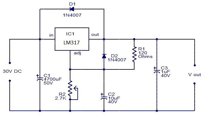
This power supply unit on the LM317 microcircuit does not require any special knowledge for assembly, and after correct installation from serviceable parts, does not need adjustment. Despite its apparent simplicity, this unit is a reliable power supply for digital devices and has built-in protection against overheating and overcurrent. The microcircuit has over twenty transistors inside and is a high-tech device, although from the outside it looks like an ordinary transistor.
The power supply of the circuit is designed for voltages up to 40 volts AC, and the output can be obtained from 1.2 to 30 volts DC, stabilized voltage. Adjustment from minimum to maximum with a potentiometer is very smooth, without jumps and dips. Output current up to 1.5 amperes. If the current consumption is not planned to be higher than 250 milliamperes, then a radiator is not needed. When a larger load is consumed, place the microcircuit on a heat-conducting paste to a radiator with a total dissipation area of \u200b\u200b350 - 400 or more, square millimeters. The selection of a power transformer must be calculated on the basis that the voltage at the input to the power supply must be 10-15% higher than you plan to receive at the output. It is better to take the power of the supply transformer with a good margin, in order to avoid excessive overheating and it is imperative to put a fuse at its input, matched by power, to protect against possible troubles.
For the manufacture of this necessary device, we need the following parts:
- Chip LM317 or LM317T.
- Almost any rectifier assembly or individual four diodes for a current of at least 1 ampere each.
- Capacitor C1 from 1000 MkF and above with a voltage of 50 volts, it serves to smooth out voltage surges in the supply network, and the larger its capacity, the more stable the output voltage will be.
- C2 and C4 - 0.047 MkF. The number 104 on the condenser cover.
- C3 - 1MkF and more with a voltage of 50 volts. This capacitor can also be used with a larger capacity to increase the stability of the output voltage.
- D5 and D6 are diodes, for example 1N4007, or any others for a current of 1 amp or more.
- R1 - potentiometer 10 Kom. Any type, but always good, otherwise the output voltage will "jump".
- R2 - 220 Ohm, 0.25 - 0.5 watts.
Assembling a regulated regulated power supply
I made the assembly on a regular breadboard without any etching. I like this method because of its simplicity. Thanks to him, the circuit can be assembled in a matter of minutes.


Checking the power supply
By rotating the variable resistor, you can set the desired output voltage, which is very convenient.The master, whose device description in the first part, having set himself the goal of making a power supply with adjustment, did not complicate his business and simply used the boards that were idle. The second option involves the use of even more common material - an adjustment was added to the usual block, perhaps this is a very promising solution in terms of simplicity, despite the fact that the necessary characteristics will not be lost and even an inexperienced radio amateur can implement the idea with his own hands. There are two more options in the bonus at all simple schemes with all detailed explanations for beginners. So, there are 4 ways to choose from.
We will tell you how to make a regulated power supply from an unnecessary computer board. The master took the computer board and cut out the block that powers the RAM.
This is how it looks.
Let's decide which parts you need to take, which ones are not, in order to cut off what is needed so that all the components of the power supply are on the board. Usually, a pulse unit for supplying current to a computer consists of a microcircuit, a controller PWM, key transistors, an output inductor and an output capacitor, an input capacitor. The board also has an input choke for some reason. He left him too. Key transistors - maybe two, three. There is a seat for 3 transistors, but it is not used in the circuit.
The controller PWM microcircuit itself may look like this. Here it is under a magnifying glass.

It may look like a square with small pins on all sides. This is a typical PWM controller found on a laptop motherboard.

This is how the switching power supply looks like on a video card.

The power supply for the processor looks exactly the same. We see the controller and several processor power channels. 3 transistors in this case. Choke and capacitor. This is one channel.
Three transistors, choke, capacitor - the second channel. 3 channel. And two more channels for other purposes.
You know what a PWM controller looks like, look under a magnifying glass for its marking, search for a datasheet on the Internet, download a pdf file and look at the diagram so as not to confuse anything.
In the diagram we see a PWM controller, but at the edges there are marked, numbered conclusions.

Transistors are indicated. This is a choke. These are the output capacitor and the input capacitor. The input voltage ranges from 1.5 to 19 volts, but the PWM controller supply voltage must be between 5 volts and 12 volts. That is, it may turn out that a separate power supply is required to power the PWM controller. All piping, resistors and capacitors, do not be alarmed. You don't need to know. Everything is on the board, you do not assemble a PWM controller, but use a ready-made one. You only need to know 2 resistors - they set the output voltage.
Resistor divider. Its whole point is to reduce the signal from the output to about 1 volt and apply feedback to the input of the PWM controller. In short, by changing the value of the resistors, we can adjust the output voltage. In the case shown, instead of the feedback resistor, the master put a 10 kilo-ohm trimmer resistor. This proved to be sufficient to regulate the output voltage from 1 volt to about 12 volts. Unfortunately, this is not possible on all PWM controllers. For example, on PWM controllers of processors and video cards, in order to be able to adjust the voltage, the ability to overclock, the output voltage is supplied by software via a multi-channel bus. It is possible to change the output voltage of such a PWM controller only with jumpers.

So, knowing what the PWM controller looks like, the elements that are needed, we can already cut out the power supply. But this must be done carefully, since there are tracks around the PWM controller that you may need. For example, you can see - the track goes from the base of the transistor to the PWM controller. It was difficult to keep it, so the board had to be carefully cut out.
Using the tester in continuity mode and focusing on the circuit, I soldered the wires. Also using the tester, I found the 6th output of the PWM controller and the resistors rang from it feedback... The resistor was rfb, it was evaporated and instead of it, a 10 kilo-ohm trimmer resistor was soldered from the output to regulate the output voltage, and also through the calls I found out that the power supply of the PWM controller is directly connected to the input power line. This means that it will not be possible to supply more than 12 volts to the input, so as not to burn the PWM controller.
Let's see how the power supply looks like in operation
Soldered the plug for the input voltage, voltage indicator and output wires. We connect an external power supply of 12 volts. The indicator lights up. Has already been set to a voltage of 9.2 volts. Let's try to adjust the power supply with a screwdriver.

It's time to check out what the power supply is capable of. Took a wooden block and a homemade wirewound resistor from nichrome wire... Its resistance is low and, together with the tester's probes, is 1.7 ohms. We turn on the multimeter in ammeter mode, connect it in series to the resistor. Look what happens - the resistor is heating up to red, the output voltage is practically unchanged, and the current is about 4 amperes.

Previously, the master has already made similar power supplies. One is cut by hand from the laptop board.

This is the so-called duty stress. Two sources for 3.3 volts and 5 volts. I made a case for him on a 3d printer. You can also look at the article where I made a similar regulated power supply, I also cut it out of the laptop board (https://electro-repair.livejournal.com/3645.html). This is also a PWM power controller for RAM.
How to make a regulating power supply from a conventional one, from a printer
We will talk about the canon printer power supply, inkjet. They are left idle for many. This is essentially a separate device, held on a latch in the printer.
Its characteristics: 24 volts, 0.7 amperes.

I needed a power supply for homemade drill... It just fits in power. But there is one caveat - if you connect it like that, we get only 7 volts at the output. Triple output, connector and we get only 7 volts. How to get 24 volts?
How to get 24 volts without disassembling the unit?
Well, the simplest is to close the plus with an average output and get 24 volts.
Let's try to do it. We connect the power supply to the 220 network. We take the device and try to measure it. We connect and see 7 volts at the output.
Its central connector is not used. If we take and connect to two at the same time, the voltage is 24 volts. This is the easiest way to make this power supply 24 volts without disassembling.
Needed homemade regulatorso that the voltage can be adjusted within certain limits. 10 volts to maximum. This is easy to do. What is needed for this? First, open the power supply itself. It is usually glued. How to open it so as not to damage the case. There is no need to poke or pry anything. We take a piece of wood more massive or there is a rubber mallet. We put it on a hard surface and peel it along the seam. The glue comes off. Then they knocked on all sides well. Miraculously, the glue comes off and everything opens up. Inside we see the power supply.

Let's get the board. Such power supply units can be easily converted to the desired voltage and can also be made adjustable. On the reverse side, if we turn it over, there is an adjustable tl431 zener diode. On the other hand, we will see the middle contact goes to the base of the q51 transistor.


If we apply voltage, then this transistor opens and 2.5 volts appears on the resistive divider, which are needed for the zener diode to work. And the output is 24 volts. This is the easiest option. How to start it can still be - throw out the q51 transistor and put a jumper instead of the r 57 resistor and that's it. When we turn it on, the output is always 24 volts continuously.
How do I make the adjustment?
You can change the voltage, make 12 volts from it. But in particular, the master does not need it. You need to make it adjustable. How to do it? We discard this transistor and instead of the resistor 57 by 38 kilo-ohms, we will put an adjustable one. There is an old Soviet one for 3.3 kilo-ohms. You can put from 4.7 to 10, which is. Only the minimum voltage to which it can lower it depends on this resistor. 3.3 is very low and unnecessary. The engines are planned to be delivered at 24 volts. And just from 10 volts to 24 volts is normal. Who needs a different voltage, you can have a large resistance trimmer.
Let's get started, we will solder. We take a soldering iron, hair dryer. I removed the transistor and resistor.

I soldered the variable resistor and try to turn it on. I applied 220 volts, we see 7 volts on our device and we begin to rotate the variable resistor. The voltage has risen to 24 volts and we rotate smoothly and smoothly, it drops - 17-15-14, that is, it drops to 7 volts. In particular, it is installed at 3.3 com. And our rework was quite successful. That is, for purposes from 7 to 24 volts, voltage regulation is quite acceptable.

This option turned out. I put a variable resistor. The handle turned out to be an adjustable power supply - quite convenient.
Video of the Tekhnar channel.
It is easy to find such power supplies in China. I came across an interesting store that sells used power supplies from various printers, laptops and netbooks. They disassemble and sell the boards themselves, completely serviceable for different voltages and currents. The biggest plus is that they disassemble proprietary hardware and all power supplies are of high quality, with good details, all have filters.
Photos - different power supplies, cost a penny, almost a freebie.
Simple block with adjustment
Simple option homemade device for power supply of devices with regulation. The scheme is popular, it is widespread on the Internet and has been shown to be effective. But there are also limitations, which are shown on the video along with all the instructions for making a regulated power supply.


Homemade regulated unit on one transistor
What is the simplest regulated power supply you can make? This can be done on the lm317 microcircuit. She already with herself is almost a power supply. It can be used to manufacture both a voltage-regulated power supply and a flow. This video tutorial shows a voltage regulated device. The master found a simple scheme. Input voltage maximum 40 volts. Output from 1.2 to 37 volts. Maximum output current 1.5 amps. 
Without a heat sink, without a heat sink, the maximum power can be as little as 1 watt. And with a 10 watt radiator. List of radio components. 
Let's start assembling


Connect an electronic load to the output of the device. Let's see how well the current holds. We set it to the minimum. 7.7 volts, 30 milliamps.
 Everything is regulated. Let's set 3 volts and add current. On the power supply, we will only set more restrictions. We translate the toggle switch to the top position. Now 0.5 amperes. The microcircuit began to warm up. There is nothing to do without a heat sink. Found some kind of plate, not for long, but that's enough. Let's try again. There is a drawdown. But the block works. Voltage regulation is in progress. We can insert an offset to this scheme.
Radioblogful video. Solder video blog.