Do-it-yourself ventilation deflector. Homemade wind generator for home and summer cottages: principles of operation, schemes, what and how to do Final assembly and installation
It is difficult not to notice how the stability of electricity supply to suburban facilities differs from the supply of city buildings and enterprises with electricity. Admit that you, as the owner of a private house or summer cottage, have repeatedly encountered interruptions, inconveniences and damage to equipment associated with them.
The listed negative situations, together with the consequences, will cease to complicate the life of lovers of natural spaces. Moreover, with minimal labor and financial costs. To do this, you just need to make a wind power generator, which we talk about in detail in the article.
We have described in detail the options for making a system that is useful in the household, eliminating energy dependence. According to our advice, an inexperienced can build a wind generator with his own hands. house master... The practical device will help you to significantly reduce your daily expenses.
Alternative energy sources are the dream of any summer resident or homeowner whose site is located far from central networks. However, receiving bills for electricity consumed in a city apartment, and looking at the increased tariffs, we realize that a wind generator created for household needs, it would not hurt us.
After reading this article, perhaps you will make your dream come true.
Wind generator - perfect solution to provide a suburban facility with electricity. Moreover, in some cases, its installation is the only possible way out.
In order not to waste money, effort and time, let's decide: are there any external circumstances that will create obstacles for us in the process of operating a wind generator?
To provide a summer cottage or a small cottage with electricity, it is enough, the power of which does not exceed 1 kW. Such devices in Russia are equated to household products. Their installation does not require certificates, permissions or any additional approvals.
Energy independence issues concern the minds of not only the leaders of states, enterprises, but also individual citizens, owners of private houses. With the increasing monopoly and tariffs of electricity producers, the people are looking for efficient alternative power sources. One such source is considered to be a wind generator.
Main elements in a wind generator system
There are many models, options from different manufacturers, but as practical experience shows, they are not always available in price and quality for a wide range of consumers. If you have information, certain knowledge of electrical engineering and practical skills, it is possible to make a wind generator with your own hands.
Operating principle and basic elements
The work of a home-made wind generator is no different from industrial models, the principles of operation are the same. Wind energy is converted into mechanical energy by rotating the rotor of a generator that generates electricity.
Main structural elements (fig. Above):
- propeller with blades;
- a rotation shaft through which torque is transmitted to the generator rotor;
- generator;
- the construction of the generator mounting at the installation site;
- if necessary, to increase the rotor speed, a gearbox or belt drive can be installed between the shaft with the propeller and the generator shaft;
- to convert the alternator's alternating current to a constant one, a converter is used, a rectifier diode bridge, the current from which is supplied to recharge the battery;
- a storage battery, from which electricity is supplied through the inverter to the load;
- inverter converts d.C. battery with a voltage of 12 V or 24 V AC with a voltage of 220 V.
The designs of propellers, generators, gearboxes and other elements may vary, have various characteristics, additional devices, but the listed components are always present at the heart of the system.
Choosing and making with your own hands
By design, there are two types of axles that rotate the generator rotor:
- generators with a horizontal axis of rotation;

Generator with horizontal axis of rotation
- generators with a vertical axis of rotation.

Rotary wind turbine with vertical axis of rotation
Horizontal axes of rotation
Each design has its own advantages and disadvantages. The most common option is with a horizontal axis. These models have a high efficiency of converting wind energy into rotational movements of the axis, but there are certain difficulties in calculating and making blades with your own hands. The usual flat blade shape used in ancient windmills is ineffective.
To use the maximum wind energy during the rotation of the axis, the blades must be wing-shaped. On airplanes, the shape of the wing, due to the force of the headwind, provides lift flows. In the case under consideration, the forces of these flows will be directed to the rotation of the generator shaft. Propellers can be with two, three, or a large number of blades, most often designs with three blades. This is enough to provide the required rotation speed.
Wind turbines with a horizontal axis of rotation must be constantly turned by the plane of the propeller to the front of the headwind. This requires the use of a vane type tail unit, which, under the influence of the wind, like a sail, turns the entire structure with a propeller to the headwind.
Vertical axes of rotation
The main disadvantage of this option is its low efficiency, but this is compensated by a simpler design that does not require the manufacture of additional elements for turning the blades to the wind. The vertical arrangement of the axle and blades allows you to use wind energy for rotation from any direction; this design is easier to do with your own hands. The rotation of the shaft is more stable, without sudden jumps in speed.
Average annual wind speeds in Russia are not the same. The most favorable conditions for the operation of wind generators are 6-10 m / s. There are few such areas, mainly winds of 4-6 m / s prevail. To increase the rotation speed, it is necessary to use gearboxes and take into account the height, wind rose on the site of the generator installation.
An example of the manufacture of a wind generator
A variant with a vertical axis of rotation is being considered.
DIY wind turbine
The easiest option for making blades is to use metal barrel 50-200 liters. Depending on the number of blades required, the barrel is cut from top to bottom by a grinder into 4 or 3 equal parts.

Vertical blades from a metal barrel
You can simply use sheets of galvanized roofing iron, which are easy to cut into the desired shape with your own hands, using metal scissors.

Vertical blades made of sheet iron
Subsequently, the blades are attached to the upper part of the axis of rotation. The basis for their fastening can be wooden discs made of six-layer plywood.
It is safer to use a metal frame made of a rectangular profile, to which the blades are bolted.

Example of vertical blades placement

An example of attaching blades to a platform
The frame or discs are rigidly attached to the axis of rotation, the axis itself is inserted into couplings with bearings, which are securely installed in the frame of the tower or roof of the building on which the generator is located.
Installation of the axle with blades on the tower

Visual representation of the installation of the vertical axis of rotation on the roof of the building
- Turbine with vertical blades.
- Axle stabilization platform with double row ball bearing.
- Steel cable braces Ø 5mm.
- Vertical axis, steel pipe Ø 40-50mm, wall thickness at least 2mm.
- Rotation speed control lever.
- The blades of the aerodynamic regulator are made of plywood or plastic 3-4 mm thick.
- The rods, which regulate the rotation speed, the number of revolutions.
- A weight whose weight sets the speed of rotation.
- Vertical axle pulley for belt transmission, bicycle rim from the wheel is widely used, without tube and tire.
- Support bearing.
- Pulley on the generator rotor axis.
A pulley for a belt drive or a gear for a gearbox is attached to the lower end of the axle, this is necessary to increase the rotor speed. Practice shows that at a wind speed of 5 m / s, the rotation of the shaft with horizontal blades from the barrel will not exceed 100 rpm. With a wind speed of 8-10 m / s, the rotation reaches up to 200 m / s. This is very little for the generator to provide the necessary power to charge the battery.
The gearbox with a ratio of 1:10 allows you to achieve the required rotation speed.

Installing belt pulleys
Low speed generator
The easiest way to convert mechanical rotational energy into electricity is car generators... But ordinary generators from passenger cars for wind turbines are not recommended due to the presence of brushes in their design. Graphite brushes remove the current induced on the rotor; during operation, they are erased and require replacement. In addition, such generators are high-speed; to generate a voltage of 14 V with a current of up to 50 A, 2000 or more revolutions are required.
More efficient generators for wind turbines from tractors and buses Г.964.3701 with magnetic excitation of windings. They have no brushes and operate at lower speeds. The G288A.3701 generator has three phases, it is used to supply power to vehicles in conjunction with a battery. Has good characteristics for use in wind turbine systems:
- generates a voltage of 28 V;
- built-in rectifier provides direct current up to 47 A;
- output power up to 1.3 kW;
- idling rotation 1200 rpm;
- with a current load of 30A, 2100 rpm is required.
The generator has suitable dimensions and weight:
- total weight 10 kg;
- diameter 174 mm;
- length 230 mm.

Generator with MAZ - 24V
Generators of this type are used in transport KAMAZ, Ural, KRAZ, MAZ with engines of the Yaroslavl plant YaMZ 236, 238, 841, 842 and ZMZ 73. In order to save money, you can buy a used generator at disassembly points. To generate more power of electricity at low speeds, you can make a generator with your own hands on nyodymium magnets, but this is a separate topic and requires a more detailed description.
Assembly sequence
- First of all, a tower or a structure for mounting a generator on the roof of a building is mounted. The vertical axis is attached to the bushings with bearings, the blades are installed.
- After installing the axle with blades, a pulley for the belt drive is fixed on the lower part.
- At the level of the axle pulley, to a specially prepared platform, a generator with a belt pulley is attached to the rotor shaft. Alternator pulleys and paddle axles must be aligned.
The diameter of the pulley on the axle should be about 10 times the diameter of the pulley on the generator shaft. Based on the conditions that the calculated wind speed is about 10 m / s, the axis rotation speed will be up to 200 rpm.
The formula is used:
Wr \u003d Wos x Dosd, where
- Wr is the rotation speed of the generator pulley;
- Dos is the diameter of the pulley on the vertical axis;
- d - pulley diameter on the generator rotor shaft;
- Wos is the rotation speed of the vertical axis pulley.
Wr \u003d 200 rpm x 500mm / 50 mm \u003d 2000 rpm - sufficient rotation speed for the generator of the selected type to provide the required power.
- The belt is tightened; for this, there must be slots in the generator mounting platform, like on a car mount.
- The generator output wires are connected to the battery terminals.
These generators have built-in rectifiers, the output is direct current, so the positive red wire is attached to the "+" terminal, and the negative wire to the "minus" terminal.
- The input of the 24V / 220V inverter is connected to the battery, also observing the polarities.
- The inverter output connects to the load circuit.
Video. DIY wind generator.
Having necessary materials, practical skills of locksmith work, using ready-made automobile generators with magnetic excitation of windings, the wind generator is easy to install with your own hands. To manufacture a generator with a higher power on nodymium magnets, you will need a deeper knowledge of electrical engineering and skills in assembling electrical equipment. This is one of the most simple ways assemble a wind generator with your own hands.
An important condition for the full functioning of the furnace is normal draft, which will help to remove the combustion products. This indicator is strongly influenced by the diameter of the chimney. If it is of small cross-section, then the combustion products will not be able to go outside and will begin to accumulate inside the house. In the case of using a wide chimney, cold air flows will prevent burnt-out substances from rising. All these and other nuances can be compensated for by a traction amplifier, which can really be done independently
Traction enhancement options
There are several types of devices that can increase the outflow of air. Among them, the most popular are:- Deflector ... Structurally, it increases the diameter of the chimney at the outlet.
- ... A device that is installed on the top of the chimney (turns against the wind), protecting its mouth from dust and protecting it from various precipitation.
- Smoke fans ... Most often they are installed on a chimney with a small cross-section. They can be turned on when there is not enough natural wind flow.
- Rotary turbines ... Such devices are installed on the pipe head to provide free access to the wind. They are best suited for gas boilers.
But the simplest and no less effective is to lengthen the chimney pipe. This increases the difference in air pressure and increases the thrust. Typically, the chimney is 5 meters high (this distance includes the vertical section of the chimney without taking into account elbows, slopes and narrowings).
If the roof has a sharp slope or large objects are located near it, then these circumstances worsen the draft, which will help to overcome the increase in the chimney length. But with a very long pipe, there may be heat losses, which will not be used to heat housing, but to heat cold street air. To prevent this from happening, special dampers are provided in the furnace that regulate the amount of gas removed.
Do-it-yourself deflector installation
The device optimizes air extraction by being a reflective device. It will not be difficult to complete it yourself - it is enough to arm yourself necessary tool and purchase galvanized metal sheets. Their thickness should be no more than 1 mm.The simpler the design of the deflector, the more accurate the drawings and more efficient device... No need to come up with an intricate shape. For example, the most elementary scheme is taken. Dimension D is the diameter of the pipe with a small gap so that the deflector can be securely fixed on it. Di - twice the chimney cross section.

Needed tools:
- roulette;
- electric drill;
- clamps;
- hammer;
- square;
- scissors for metal, hacksaw or grinder;
- riveter;
- heat-resistant mastic;
- self-tapping screws;
- parts for fasteners.
- Apply the dimensions of the blanks to the metal sheet. Cut them out.
- Roll up the future nozzle body into a ring and fasten its edges with rivets or self-tapping screws.
- Assemble the cone for connection to the chimney in the same way.
- Combine both products. For better sealing, treat their joints with mastic.
- Build a metal umbrella and secure it on top of the deflector with pins or rivets, if it is made on the legs.
- Strengthen the stability of the structure by using clamps.
Weather vane to increase thrust
This amplifier, unlike the previous one, can rotate around the chimney. The principle of operation of the device lies in its response to air currents, as a result of which the thrust amplifier takes the appropriate direction from any gust of wind. Air is blown into special grids, which creates a constant vacuum in the pipe.
The demonstrated product can work in any weather conditions. It responds even to a slight breeze. The invented device improves the efficiency of the combustion boiler by about 20%. If you install it on a pipe, you will not need to make the chimney very long, you can shorten the part visible above the roof.
The weather vane is an exhaust device for the ventilation system, therefore it can be used for apartment buildings and private houses. It gained particular popularity when installing gas boilers. The device not only enhances the draft, but also prevents the boiler from damping.
Electric fans
Powerful fans that are used for fireplaces and wood-burning stoves. They are designed to operate in hot environments where ash and other combustion products are high.
The body of such devices is made of galvanized steel with a specially applied polymer coating, which provides it with protection against aggressive environments. It has a protective grill that prevents various large and medium objects from entering the duct.
Working ventilation device from a single-phase motor, which can ensure uninterrupted operation of the system in any weather. Although it has protection against the flow of hot air, for safety reasons it is placed outside the zone of its movement. It has ventilation holes and a special wheel that prevents soot and dust from sticking.
Such a ventilated system is fully automated. It has built-in temperature sensors, as well as their analogs, which regulate the force of the air flow. They respond to deviations in the operation of the electric motor and create optimal traction for the device.
Their principle of operation is similar to the deflector - they are also located at the top of the pipe and use wind energy. The nozzle, on which the grates with wings are located, rotates in one direction, regardless of the direction of the wind. Due to its movement, it creates the necessary air rarefaction. The design of the device resembles a dome and is able to protect the chimney from debris and precipitation. It is designed for gas boilers and ventilation ducts. Not recommended for solid fuel boilers and fireplaces.

In calm weather, this amplifier does not work, but in the summer, when the boiler is not functioning, it can create a very strong draft, which is often unnecessary.
Description and operation diagram of the traction amplifier (video)
In the next video, experts will talk about the amplifier, as well as how it works. At the same time, they will indicate the advantages of this method of removing combustion products.Which of the proposed devices to choose will help to decide the very design of the flue duct and the type of boiler that heats the house. They can be used if the length of the pipe cannot be increased.
The set of necessary communications to ensure comfortable conditions in a building of any purpose involves, among other things, the device of a ventilation system. Ideally, it should be non-volatile - this is very important in modern conditions without stopping the rising energy prices. That is why, even at the design stage of communications, natural ventilation is primarily considered. At the same time, the correct approach to the technological solution of the system is a rotary deflector integrated into the ventilation duct.
There can be no problems with cravings
The meaning of any ventilation system is to remove polluted air and excess moisture from the premises, that is, to ensure normal air exchange. This will be the case if the ventilation duct functions efficiently and correctly - the draft is excellent. If there are problems in this regard, then they are often provoked by rain, snow, wind masses falling into the channel shaft. Also, poor traction can be caused by incorrect positioning. ventilation pipe, its insufficient height or incorrectly selected duct diameter. The installation of a rotary deflector is designed to eliminate such shortcomings of natural ventilation.
Reference. The rotary deflector also has other names - turbo deflector or rotary turbine. This is a complex mechanism with a rotating part - an active head equipped with a special system of blades. Also, the structure has a static part - the base to which the head is attached and connected to the ventilation pipe.
The benefits of a rotary deflector

- Regardless of the direction of the wind, the active head rotates in the same direction. As a result, the effect of "partial vacuum" in the ventilation duct is obtained - the air is rarefied, the force of the flow increases, and the risk of reverse thrust is close to zero.
- Rotary models completely exclude the influence of external factors on the ventilation efficiency - precipitation and gusty wind.
- The autonomy of the functioning of a mechanical device that increases the performance of the air exchange system is one of its most important advantages.
- Low costs for modernization of ventilation.
- Rapid return on investment for a turbine deflector.
- Protection of the ventilation mine from the ingress of debris, birds, etc.
- The decorative completeness of the pipe brought out to the roof - any facade benefits from the presence of such a spherical object.
Important! The rotary deflector increases the efficiency of a standard natural supply and exhaust ventilation system by 2-4 times. In this case, "amplification" does not require connection to the power supply, which corresponds modern trends energy efficiency of buildings and structures.
What are the disadvantages of a turbo deflector

The rotary design is weather-dependent - this is actually the only, but very important disadvantage of it. In calm weather, the turbo deflector is essentially no different from the usual protective visor on the duct pipe.
Is it possible to make a rotary deflector with your own hands
Simpler types of deflectors, used in practice for a long time, are often made by skilled householders on their own. In principle, a technically savvy person can handle this job. True, for this it will be necessary to develop a working drawing of the future design, correctly take measurements, and develop a scheme for mounting the deflector.

Regarding the turbocharged variation, not everything is so simple - it is technically a more complex design. Therefore, almost always, having decided to use the rotary model, they acquire it in the form of a professionally made product.
What the market offers
Turbovent
The range of rotary deflectors of this brand is represented by models of different geometric shapes, in terms of the immovable base:
- A - round pipe;
- B - square tube;
- C - square flat base.
Product marking in the assortment is presented as TA-315, TA-355, TA-500. The digital index indicates the diameter of the round or the parameters of rectangular bases. It is by them that one can judge the dimensions of the mechanism, as well as the scope of its application. For example, TA-315 and TA-355 are relevant when organizing air exchange in the under-roof space. But the TA-500 is a universal device and can be integrated into the ventilation of a residential building.

The rotary deflector "Turbovent" is produced in Russia - in the Nizhny Novgorod region, in the city of Arzamas.
Rotowent
Deflectors made of stainless steel made in Poland. Suitable for all roof configurations. Products are made of high quality stainless steel. The devices are universal - suitable for both ventilation systems and chimneys. The boundary indicator of the operating temperature is 500 C.
Turbomax
Rotary deflector manufactured by a company from the Republic of Belarus. The manufacturer positions its products as the Turbomax1 rotary chimney hood. But it is also suitable for ventilation. It can be safely used in areas with II and III wind load zones. The company focuses the attention of consumers on the fact that they are ready to manufacture a product to order according to the parameters for a specific object.
Installation features
Factory turbo deflector - one-piece design, ready for installation. It has an active movable top and a base containing zero resistance bearings. The product is thought out in such a way that even in a strong gusty wind it will not tilt or carry it down.

Attention! When installing, it is important to take into account that the deflector of any modification must rise 1.5-2.0 m above the roof. ventilation duct will intensify.
In conclusion, we would like to note that rotary deflectors in their segment are the most expensive. At the same time, the consumer is invited to choose a suitable structure made of stainless steel, galvanized or structural steel with a protective polymer coating, the color of which can be matched to the facade design. Of course, the type of material from which the deflector is made affects its cost.
I found this detailed design of the Savonius-type rotary wind generator on this wonderful site here http://mirodolie.ru/node/2372 After reading the material, I decided to write about this design and how everything was done.
How it all began
The idea to build a wind generator originated back in 2005, when a plot was received in the family estate of Mirodolye. There was no electricity and everyone solved this problem in their own way, mainly through solar panels and gas generators. As soon as the house was built, the first thing to do was to think about lighting, and it was purchased solar panel 120 watts. In the summer it worked well, but in the winter its efficiency dropped dramatically and on cloudy days it gave a current of only 0.3-0.5A / h, this did not suit in any way, since it was barely enough even for light, and it was also necessary to power the laptop and other small electronics.Therefore, it was decided to build a wind generator to use also wind energy. At first there was a desire to build a sailing wind turbine. I really liked this type of wind turbine, and after some time spent on the Internet, a lot of materials on these wind generators have accumulated in my head and on the computer. at least five meters.
There was no way to pull a large wind generator, but still I really wanted to try to make a wind generator, at least of small power, to charge the battery. The horizontal propeller wind generator immediately disappeared since they are noisy, there are difficulties with the manufacture of slip rings and protection of the wind generator from strong windand it is also difficult to make the correct blades.
I wanted something simple and slow-moving, after watching some videos on the Internet, I really liked the Savonius-type vertical wind generators. In fact, these are analogs of a cut barrel, the halves of which are moved apart in opposite directions. In search of information, I found a more advanced type of these wind generators - the Ugrinsky rotor. Ordinary Savonius have a very small KIEV (wind energy utilization factor), it is usually only 10-20%, and the Ugrinsky rotor has a higher KIEV due to the use of wind energy reflected from the blades.
Below are pictorial pictures for understanding the principle of robots of this rotor
Blade coordinates marking scheme
 >
>
The KIEV of the Ugrinsky rotor is declared up to 46%, which means that it is not inferior to horizontal wind generators. Well, practice will show what and how.
Blade manufacturing.
Before embarking on the manufacture of the rotor, models were first made from beer cans of two rotors. One model of the classic Savonius, and the Second Ugrinsky. On the models it was noticeable that the rotor of Ugrinsky works noticeably at higher speeds in comparison with the Savonius, and a decision was made in favor of Ugrinsky. It was decided to make a double rotor, one above the other with a turn at 90 degrees to achieve smoother torque and a better start.The materials for the rotor are the simplest and cheapest. The blades are made of 0.5mm thick aluminum sheet. Three circles are cut out of 10mm plywood. The circles were traced from the picture above and grooves were made 3 mm deep to insert the blades. The attachment of the blades is made at small corners and tightened with bolts. In addition, for the strength of the entire assembly, the plywood discs are tightened with studs at the edges and in the center, it turned out to be very rigid and durable.
 >
>
 >
>
The size of the resulting rotor is 75 * 160cm, about 3600 rubles were spent on the materials of the rotor.
Generator manufacturing.
Before making a generator, there were many searches for a ready-made generator, but they are almost not on sale, and what can be ordered via the Internet cost a lot of money. Have vertical wind turbines low speed and on average for this design about 150-200 rpm. And for such turns it is difficult to find something ready-made and does not require a multiplier.In search of information on the forums, it turned out that many people make generators themselves and there is nothing difficult about it. The decision was made in favor of a homemade generator for permanent magnets... It was based on the classic design of a permanent magnet axial generator, made on a car hub.
The first step was to order 32 neodymium magnets washers for this generator in the amount of 10 * 30mm. While the magnets were running, other parts of the generator were made. After calculating all the dimensions of the stator for the rotor, which is assembled from two brake discs from a VAZ car on the rear wheel hub, coils were wound.
A simple manual machine was made for winding the coils. The number of coils is 12, three per phase, since the generator is three-phase. The rotor disks will have 16 magnets each, this ratio is 4/3 instead of 2/3, so the generator will turn out to be slower and more powerful.
A simple machine is made for winding the coils.
 >
>
The locations of the stator coils are marked on the paper.
 >
>
A plywood mold is made to fill the stator with resin. Before pouring, all the coils were soldered into a star, and the wires were brought out through the cut channels.
 >
>
Stator coils before filling.
 >
>
Freshly poured stator, before pouring a glass mesh circle was laid on the bottom, and after laying the coils and pouring epoxy resin a second circle was laid on top of them, this is for additional strength. Talc is added to the resin for strength, which makes it white.
 >
>
The magnets on the disks are also filled with resin.
 >
>
And here is the already assembled generator, the base is also made of plywood.
 >
>
After manufacturing, the generator was immediately twisted by hands on the object current-voltage characteristic... It was connected to a 12 volt motorcycle battery. A handle was attached to the generator and looking at the second hand and rotating the generator some data was obtained. The battery at 120 rpm turned out to be 15 volts 3.5A, the strong resistance of the generator does not allow it to spin faster by hand. Maximum idle at 240 rpm 43 volts.
Electronics
 >
>
For the generator, a diode bridge was assembled, which was packed in a case, and two devices were mounted on the case: a voltmeter and an ammeter. Also, a familiar electronics engineer soldered a simple controller for him. The principle of the controller is simple, when the batteries are fully charged, the controller connects an additional load, which consumes all excess energy so that the batteries do not overcharge.
The first controller soldered to friends did not quite suit, so a more reliable software controller was soldered.
Installation of a wind generator.
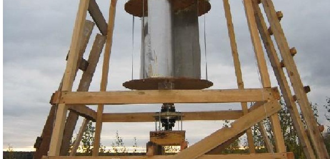
For the wind generator, a powerful frame was made of wooden bars 10 * 5 cm. For reliability, the support bars were dug into the ground by 50 cm, and the whole structure was additionally reinforced with stretch marks that were tied to the corners driven into the ground. This design is very practical and quick to install, as well as easier to manufacture than welded. Therefore, it was decided to build from wood, but metal is expensive and there is nowhere to include welding yet. >
>
Here is a ready-made wind generator. In this photo the generator drive is direct, but later a multiplier was made to raise the generator speed.
 >
>
 >
>
The generator is driven by a belt, the gear ratio can be changed by replacing the pulleys.
 >
>
 >
>
 >
>
Subsequently, the generator was connected to the rotor through a multiplier. In general, the wind generator produces 50 watts in a wind of 7-8 m / s, charging starts in a wind of 5 m / s, although it starts to rotate in a wind of 2-3 m / s, but the speed is too low to charge the battery.
In the future, it is planned to raise the wind generator higher and recycle some units of the installation, and it is also possible to manufacture a new larger rotor.