Do-it-yourself step-by-step diagram of the Lanzar amplifier. Setting up a Lanzar power amplifier - circuit diagram of a power amplifier, description of the circuit diagram, recommendations for assembly and adjustment. Some denominations require special explanations
ULF Lanzar is an amplifier built according to a classical symmetrical circuit, operating in class AB. Many car amplifiers are assembled according to a similar scheme. The simple circuit, easy assembly and configuration of this amplifier on numerous forums is a guarantee of success for beginning amplifier builders. It is enough for the arms to grow from the right places, all that remains is to solder everything correctly and set the quiescent current, that’s the whole setup. Therefore, after assembling amplifiers on microcircuits (TDA7294), the next step may well be Lanzar. The sound is quite decent, unpretentious and durable, can be used to work with subwoofers. Bipolar and field-effect transistors can be used as output transistors.
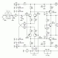
ULF Lanzar circuit

Ever since Interlavka, it became a custom to make Lanzars using this kind of wiring. Uh-uh, in light of the latest trends in PCB wiring, it’s just terrible...

The circuits of the power and ground buses are very long, and the power conductors are thin; they must be routed exactly the opposite way. Although, once upon a time, the first ULF I assembled and worked was Lanzar with all these shortcomings). And then I made some progress in mastering PCB layout in P-CAD, taking into account the recommendations on the forums. The result is Lanzar on field patches, double-sided PP, the top layer is mostly green in the form of a solid polygon. It turned out compact and according to Feng Shui)

Board layout on bipolars with one output pair:

First, we check the correctness of the wiring with LUT, otherwise you will miss the jamb and it will multiply when ordering the PP at the factory... This is how the Lanzar ULF on one pair of bipolars looks assembled. The PP is double-sided, so I had to fiddle with the iron, aligning the printouts to the control points with pins. In general, it worked out fine and the channels launched immediately.

Since there were no errors in the wiring, you can order the PCB from the production, because The series was not planned yet, so to save money without a mask and markings:

The question is regularly asked: “How to wind output coil". Simple: take a drill (mandrel) with a diameter of 5.7-5.8 mm, an enamel wire of 1-1.1 mm, wind 8 turns there and 7 turns back. We clean it, shape it after planting, everything is ready.
Lanzar also split it into two pairs of bipolars, soldered them and launched them half-turned:

The photo was preserved only without the ends, because I didn’t have time to solder it, the amplifier “found” a new owner)

Amplifier Lanzar. The repetition of the same questions on every page of discussion about this amplifier prompted me to write this short sketch. Everything written below is my idea of what a novice radio amateur needs to know who decides to make this amplifier, and does not claim to be the absolute truth.
Let's say you are looking for a good transistor amplifier circuit. Circuits such as “UM Zueva”, “VP”, “Natalie”, and others seem complicated to you, or you have little experience in assembling them, but you want good sound. Then you have found what you were looking for! Amplifier Lanzar It is an amplifier built according to a classic symmetrical circuit, with an output stage operating in class AB, and has a pretty good sound, without complicated settings and scarce components.
Amplifier circuit:
I found it necessary to make some minor changes to the original circuit: the gain was slightly increased - up to 28 times (R14 was changed), the values of the input filter R1, R2 were changed, and also, on the advice of MayBe I'm a Leo, the resistor values of the base divider of the thermal stabilization transistor (R15 , R15') for smoother adjustment of the quiescent current. The changes are not critical. The numbering of elements has been preserved.
Amplifier power
Amplifier power supply- the most expensive link in it, so you should start with it. Below are a few words about IP.
Based on the load resistance and the desired output power, the desired supply voltage is selected (Table 1). This table was taken from the original source site, however, I personally would strongly not recommend operating this amplifier at powers of more than 200-220 Watts.
REMEMBER! This is not a computer, no super-cooling is needed, the design should not work at the limit of its capabilities, then you will get a reliable amplifier that will work for many years and delight you with sound. We decided to make a high-quality device, and not a bouquet of New Year’s fireworks, so let all sorts of “squeezers” go through the forest.
For supply voltages below ±45 V/8 Ohm and ±35 V/4 Ohm, the second pair of output transistors (VT12, VT13) can be omitted! At such supply voltages, the Lanzar amplifier receives an output power of about 100 W, which is more than enough for a home. I note that if you install 2 pairs at such voltages, the output power will increase by a very insignificant amount, on the order of 3-5 W. But if “the toad is not strangling,” then in order to increase reliability, you can install 2 pairs.
Transformer power can be calculated using the PowerSup program. A calculation based on the fact that the approximate efficiency of the amplifier is 50-55%, which means that the power of the transformer is equal to: Ptrans = (Pout * N channels * 100%) / efficiency is applicable only if you want to listen to a sine wave for a long time. In a real music signal, unlike a sine wave, the ratio of peak to average values is much smaller, so there is no point in spending money on extra transformer power that will never be used anyway.
In the calculation, I recommend choosing the “heaviest” peak factor (8 dB), so that your power supply does not bend if you suddenly decide to listen to music with such a p-f. By the way, I also recommend calculating the output power and supply voltage using this program. For the Lanzar dU amplifier, you can choose about 4-7 V.
More details about the “PowerSup” program and the calculation method are written on the author’s website (AudioKiller).
All this is especially true if you decide to buy a new transformer. If you already have it in your bins, and suddenly it turns out to have more power than the calculated one, then you can safely use it, a reserve is a good thing, but there is no need for fanaticism. If you decide to make a transformer yourself, then on this page of Sergei Komarov there is a normal calculation method.
The circuit itself of the simplest bipolar power supply looks like this:
The circuit itself and the details for its construction are well described by Mikhail (D-Evil) in TDA7294.
I will not repeat myself, I will only note an amendment about the power of the transformer, described above, and about the diode bridge: since the Lanzar amplifier can have a supply voltage higher than the TDA729x, the bridge must “hold” a correspondingly higher reverse voltage, no less:
Urev_min = 1.2*(1.4*2*Uhalf-winding_of the transformer) ,
where 1.2 is the safety factor (20%)
And with large transformer powers and capacitances in the filter, in order to protect the transformer and bridge from colossal inrush currents, the so-called. “soft start” or “soft start” scheme.
Amplifier parts
A list of parts for one channel is attached in the archive in the file
Some denominations require special explanation:
C1– separation capacitor, Lanzar amplifier must be of good quality. There are different opinions on the types of capacitors used as isolation capacitors, so those experienced will be able to choose the best option for themselves. For the rest, I recommend using polypropylene film capacitors from well-known brands such as Rifa PHE426, etc., but in the absence of such, widely available lavsan K73-17 are quite suitable.
The lower limit frequency, which will be amplified, also depends on the capacitance of this capacitor.
In the printed circuit board, as C1, there is a seat for a non-polar capacitor, composed of two electrolytes, connected with “minuses” to each other and “pluses” in the circuit and shunted by a 1 μF film capacitor:
Personally, I would throw out the electrolytes and leave one film capacitor of the above types, with a capacity of 1.5-3.3 μF - this capacity is enough to operate the amplifier at “wideband”. In the case of working with a subwoofer, a larger capacity is required. Here it would be possible to add electrolytes with capacities of 22-50 μF x 25 V. However, the printed circuit board imposes its own limitations, and a 2.2-3.3 μF film capacitor is unlikely to fit there. Therefore, we set 2x22 uF 25 V + 1 uF.
R3, R6– ballast. Although initially these resistors were chosen to be 2.7 kOhm, I would recalculate them to the required supply voltage of the amplifier using the formula:
R=(Ushoulder – 15V)/Ist (kOhm) ,
where Ist – stabilization current, mA (about 8-10 mA)
L1– 10 turns of 0.8 mm wire on a 12 mm mandrel, everything is lubricated with superglue, and after drying, resistor R31 is placed inside.
Electrolytic capacitors C8, C11, C16, C17 must be designed for a voltage no lower than the supply voltage with a margin of 15-20%, for example, at ±35 V capacitors of 50 V are suitable, and at ±50 V you need to choose 63 Volts . The voltages of other electrolytic capacitors are indicated in the diagram.
Film capacitors (non-polar) are usually not made rated for less than 63 V, so this should not be a problem.
Trimmer resistor R15 – multi-turn, type 3296.
For emitter resistors R26, R27, R29 and R30 – the board provides seats for wire-wound ceramic SQP resistors with a power of 5 W. The range of acceptable values is 0.22-0.33 Ohm. Although SQP is far from the best option, it is affordable.
The Lanzar amplifier also requires the installation of domestic resistors C5-16. I haven't tried it, but they might even be better than SQP.
The remaining resistors are C1-4 (carbon) or C2-23 (MLT) (metal film). All except those indicated separately - at 0.25 W.
Some possible replacements:
- Paired transistors are replaced with other pairs. Composing a pair of transistors from two different pairs is unacceptable.
- VT5/VT6 can be replaced with 2SB649/2SD669. It should be noted that the pinout of these transistors is mirrored relative to the 2SA1837/2SC4793, and when using them, they must be rotated 180 degrees relative to those drawn on the board.
- VT8/VT9– on 2SC5171/2SA1930
- VT7– on BD135, BD137
- Transistors of differential stages (VT1 and VT3), (VT2 and VT4) It is advisable to select pairs with the smallest beta spread (hFE) using a tester. An accuracy of 10-15% is quite enough. With a strong scatter, a slightly increased level of direct voltage at the output is possible. The process is described by Mikhail (D-Evil) in the FAK on the VP amplifier
Another illustration of the beta measurement process:
Transistors 2SC5200/2SA1943 are the most expensive components in this circuit and are often counterfeited. Similar to the real 2SC5200/2SA1943 from Toshiba, they have two break marks on top and look like this:
It is advisable to take identical output transistors from the same batch (in Figure 512 is the batch number, i.e., say both 2SC5200 with number 512), then the quiescent current when installing two pairs will be distributed more evenly across each pair.
Printed circuit board
The corrections on my part were mainly of a cosmetic nature; some errors in the signed values were also corrected, such as mixed up resistors for the thermal stabilization transistor and other little things. The board is drawn from the parts side. There is no need to mirror to make LUTs!
- IMPORTANT! Before soldering, each part must be checked for serviceability, the resistance of the resistors is measured to avoid errors in the nominal value, the transistors are checked with a continuity tester, and so on. It is much more difficult to look for such errors later on the assembled board, so it is better to take your time and check everything. Save a LOT of time and nerves.
- IMPORTANT! Before soldering in the tuning resistor R15, it must be “unscrewed” so that its full resistance is soldered into the gap in the track, i.e., if you look at the picture above, between the right and middle terminals. all the resistance of the trimmer.
- Jumpers to avoid accidental short circuit. It is better to do it with insulated wires.
- Transistors VT7-VT13 are installed on a common radiator through insulating gaskets - mica with thermal paste (for example, KPT-8) or Nomakon. Mica is more preferable. VT8, VT9 indicated in the diagram are in an insulated housing, so their flanges can simply be lubricated with thermal paste. After installation on the radiator, the tester checks the transistor collectors (middle legs) for the absence of short circuits. with radiator.
- Transistors VT5, VT6 also need to be installed on small radiators - for example, 2 flat plates measuring about 7x3 cm, in general, install whatever you find in the bins, just don’t forget to coat it with thermal paste.
- For better thermal contact, the transistors of the differential stages (VT1 and VT3), (VT2 and VT4) can also be lubricated with thermal paste and pressed against each other with heat shrink.
First launch and setup
Once again, we carefully check everything, if everything looks normal, there are no errors, “snot”, short circuits to the radiator, etc., then you can proceed to the first start.
IMPORTANT! The first startup and setup of any amplifier must be carried out with input shorted to ground, power supply current limited and no load . Then the chance of burning something is greatly reduced. The simplest solution that I use is incandescent lamp 60-150 W connected in series with the primary winding of the transformer:
We run the amplifier through the lamp, measure the DC voltage at the output: normal values are no more than ±(50-70) mV. “Walking” constant within ±10 mV is considered normal. We control the presence of voltages of 15 V on both zener diodes. If everything is normal, nothing exploded or burned, then we proceed to the setup.
When starting a working amplifier with a quiescent current = 0, the lamp should flash briefly (due to the current when charging the capacitors in the power supply), and then go out. If the lamp is bright, it means something is faulty, turn it off and look for the error.
As already mentioned, the amplifier is easy to configure: you only need to set the quiescent current (TC) of the output transistors.
It should be set on a “warm up” amplifier, i.e. Before installation, let it play for a while, 15-20 minutes. During installation of the TP, the input must be short-circuited to ground and the output suspended in the air.
The quiescent current can be found by measuring the voltage drop across a pair of emitter resistors, for example on R26 and R27 (set the multimeter to the limit of 200 mV, probes on the emitters VT10 and VT11):
Respectively, Ipok = Uv/(R26+R26) .
Next, SMOOTHLY, without jerking, turn the trimmer and look at the multimeter readings. It is required to set 70-100 mA. For the resistor values indicated in the figure, this is equivalent to the multimeter reading (30-44) mV.
The light bulb may begin to glow a little. Let's check the DC voltage level at the output again, if everything is normal, you can connect the speakers and listen.
Other useful information and possible troubleshooting options
Self-excitation of the amplifier: Indirectly determined by the heating of the resistor in the Zobel circuit - R28. Reliably determined using an oscilloscope. To eliminate this, try increasing the ratings of correction capacitors C9 and C10.
High level of DC component at the output: select transistors of the differential stages (VT1 and VT3), (VT2 and VT4) according to “Betta”. If it doesn’t help, or there is no way to choose more precisely, then you can try changing the value of one of the resistors R4 and R5. But this solution is not the best; it is still better to choose transistors.
Option to slightly increase sensitivity: You can increase the sensitivity of the amplifier (gain) by increasing the value of resistor R14. Coef. gain can be calculated by the formula:
Ku = 1+R14/R11, (once)
But you shouldn’t get too carried away, since with an increase in R14, the depth of the feedback decreases and the unevenness of the frequency response and SOI increases. It is better to measure the output voltage level of the source at full volume (amplitude) and calculate what Ku is needed to operate the amplifier with the full output voltage swing, taking it with a margin of 3 dB (before clipping).
For specifics, let the maximum to which it is tolerable to raise Ku is 40-50. If you need more, then make a preamplifier.
Download: Printed circuit board
Download all files in one archive:
Assembly of the LANZAR power amplifier
Photo sent by Alexander (Allroy), Novorossiysk
By chance, I received a “modernized” power amplifier “Oda-UM102S”. The modernization was carried out by an unknown master so severely that only good “meaty” radiators remained alive. So I decided to adapt my new project to them, which smoothly flowed out of the desire to try out a new idea in hardware.
 Historical reference
The Oda 102 Stereo stereo radio complex has been produced by the Murom RIP plant since 1986. The complex provided reception of mono and stereo broadcasts in the VHF range, recording of mono and stereo programs, with subsequent playback. The complex consisted of 5 functionally complete units: VHF tuner “Oda-102S”, cassette recorder-set-top box “Oda-302S”, power amplifier “Oda UM-102S”, pre-amplifier “Oda UP-102S” and 2 acoustic systems "15AS-213".
Fragment excluded. Our magazine exists on donations from readers. The full version of this article is available only
How to make L1 I, but if this option bothers anyone, then the coil can be wound on a 2-watt 10-33 Ohm resistor with a wire with a diameter of 0.8 mm in one layer.
VT5, VT6 are equipped with small radiators, which are an aluminum plate 10x20 mm.
--
Thank you for your attention!
Igor Kotov, editor-in-chief of Datagor magazine
Thank you for your attention!
Andrey Zelenin,
Kyrgyzstan, Bishkek
Having a powerful, high-quality subwoofer is the desire of every car enthusiast who values high-quality, loud sound and deep low frequencies (bass). The project was implemented in the summer of 2012 and took as much as 3 months; this delay was due to the shortage of many components that were used in the project. The device is a complex of amplifiers with a total power of about 750-800 watts. In several articles I will try to explain in detail the design of a subwoofer amplifier using the Lanzar circuit.
A voltage converter, a filter-adder, a stabilizer block and dynamic head protection are the component parts for the operation of such an amplifier. The voltage converter produces 500 watts of power, and all of these 500 watts are used to power the main amplifier. The lanzar's power can reach up to 360-390 watts, although the maximum power is obtained with increased power and is quite dangerous for individual parts of the amplifier.
Such an amplifier powers a powerful homemade subwoofer based on a SONY XPLOD dynamic head with a rated power of 300-350 watts, maximum (short-term power) up to 1000 watts. In a separate article we will look at the process of making a subwoofer box and all the subtleties associated with it. The case was used from a DVD player and fit perfectly. To cool the main amplifier, a huge heat sink from a Soviet radio amplifier was used. There is also a high-speed laptop cooler to remove warm air from the case.

Let's start looking at the design with a voltage converter, since this is what will need to be done first. The entire operation of the structure depends on the accurate operation of the converter. It provides a bipolar output voltage of 60 volts per arm - this is exactly what is needed to provide the specified output power of the amplifier.


The voltage converter, despite its simple design, develops a power of 500 watts, and in force majeure situations up to 650 watts. TL494 is a two-channel PWM controller, a rectangular pulse generator tuned to a frequency of 45-50 kHz is the engine of this converter, and this is where it all begins.

To amplify the output signal, a driver is assembled using low-power bipolar transistors of the BC556 (557) series.

The pre-amplified signal is fed through limiting resistors to the gates of powerful power switches. This circuit uses powerful N-channel field-effect transistors of the IRF3205 series, there are 4 of them in the circuit.

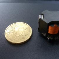
The converter transformer was initially wound on two cores (W-shaped) from the ATX power supply, but then the design changed and a new transformer was wound. Ring from an electronic transformer for powering halogen lamps (power 150-230 watts). The transformer contains two windings. The primary winding is wound with 10 strands of 0.5-0.7 mm wire at once and contains 2X5 turns. Winding is done like this. To begin, we take a test wire and wind 5 turns, stretching the turns around the entire ring. We unwind the wire and measure its length. We take measurements with a margin of 5 cm. Next, we take 10 cores of the same wire - we twist the ends of the wires. We make two such blanks - 2 buses of 10 cores each. Then we try to wind it as evenly as possible around the entire ring, you get 5 turns. Then you need to separate the tires, in the end we get two equal halves of the winding.


We connect the beginning of one winding with the end of the second winding, or vice versa - the end of the first with the beginning of the second. Thus, we have phased the windings and the circuit can be checked. To do this, we connect the transformer to the circuit, and wind a test winding (secondary) on the ring. The winding can contain any number of turns; it is better to wind 2-6 turns of 0.5-1mm wire.
The first start of the converter is best done through a 20-60 watt lamp (halogen).
After winding the test secondary winding, we start the converter. We connect an incandescent lamp with a power of a couple of watts to the test winding. The lamp should glow, while the transistors (if without heat sinks) should heat up slightly during operation.
If everything is normal, then you can wind a real winding; if the circuit does not work properly or does not work at all, then you need to turn off the gates of the transistors and use an oscilloscope to check for the presence of rectangular pulses on pins 9 and 10. If there is generation, then the problem is most likely in the transistors, if they are also normal, then the transformer is incorrectly phased, you need to change the beginning and end of the windings (phasing was discussed in part 2).


The secondary winding is wound according to the same principle as the primary winding and is phased in the same way. The winding contains 2X18 turns and is wound with 8 strands of 0.5 mm wire at once. The winding needs to be stretched across the entire ring. The midpoint tap will be the body, since we are required to obtain bipolar voltage. The output voltage is obtained at an increased frequency, so the multimeter is not capable of measuring it.
The diode rectifier in my case was assembled from powerful domestic diodes of the KD213A series. The reverse voltage of the diode is 200V, with a current of up to 10A. These diodes can operate at frequencies up to 100kHz - an excellent option for our case. You can also use other powerful pulse diodes with a reverse voltage of at least 180 Volts.