Homemade antennas: outdoor, home. How to make a digital television antenna with your own hands for the garden and at home Making a Kharchenko antenna with your own hands
Should I buy or not a decimeter antenna to watch digital TV? The question may seem strange, but upon closer examination it becomes more reasonable. So, point by point:
- Where are the guarantees that the purchased antenna is worth the money spent on its purchase?
- If you use a purchased UHF TV antenna at your dacha, you will most likely have to carry it back and forth with you to avoid theft.
- The need for such a device may arise spontaneously, somewhere at a picnic, and a trip to a special store is simply undesirable or impossible.
You can solve the problem of receiving an over-the-air television signal in the UHF range using a homemade antenna for digital TV.
Types of dvb t2 antennas
Standard t2 dmv television - currently the newest mass, used to transmit a digital signal. Its feature is a significant simplification of reception and transmission devices through the use of decoding devices, so-called tuners; some TV models already have a built-in digital signal decoding module. The requirements for signal power are significantly reduced, even a low-power signal is sufficient to reproduce a high-quality picture, so there is almost always no need for an amplifier; it becomes unnecessary.
Antenna Kharchenko
Let's consider the design of a zigzag waveguide, the design of which was proposed by the enthusiastic engineer K. P. Kharchenko back in 1961 in the magazine "Radio". Externally, this device looks like a double diamond or square adjacent to each other with open corners; the central core and braid of the coaxial cable are connected at the junction points.
To amplify the signal, you can use a metal reflector - a mirror that reflects a distant signal to the device. Digital Antenna Dimensions do it yourself depend on the wavelength of the received signal, it is clear that for the decimeter wave range the dimensions of the dvb t2 antenna with your own hands will be within a few decimeters. The higher the reception frequency, the shorter the wave, the smaller the size. The room waveguide for receiving channels will have side dimensions of approximately 11 and 15 centimeters, overall external dimensions of 30 by 17 cm, and reflector dimensions of 50 by 50 cm.
To make it, you will need a little more than a meter of conductor - copper or aluminum wire or tube with a diameter of 5-6 mm, preferably up to 10 mm, or strip, comparable width. The distance between the open points of the abutment angles is 1-2 cm, the distance to the reflector is about 5-7 cm. This will be a long-range waveguide, allowing you to receive 20 or more programs. The length of the television cable affects the performance of the antenna; if the cable is over 5-7 meters, you will need an amplifier, which one you choose.
- During operation, the waveguide should be turned towards the nearest transmitting station; during the first installation, it is worth experimenting with the orientation of the device, achieving stable signal reception.
This type of antenna can be successfully used to receive a weak cellular network signal, only the dimensions of the device will be several times smaller. There are enough online calculators on the network to calculate specific parameters for each case.
Travel antenna
To make this homemade product, in addition to a plug for connecting to a TV receiver, you only need two identical empty half-liter metal cans from under drinks. Instead of a coaxial cable, you can use regular “noodles” for landline phones. In the area of the neck of each empty and dry can, one wire of the “noodle” is secured with a self-tapping screw, or the braid of a television cable is screwed to one, and its core to the other. The banks are located on the same straight line, the reception is adjusted by changing the distance between them from 1 to 8 cm, as well as by precise orientation in the direction of the emitter. The device should not be too close to the TV.
 If you don’t want to bother with any handicrafts, and it’s a pity to spend extra money, then you can arrange a very simple device. But it will work stably where the signal level is quite high. You will need to know the digital broadcast frequency to determine the wavelength. To do this, 300 is divided by the number of megahertz of the “digital” broadcast frequency and a fairly accurate value in meters is obtained. For a frequency of 480 MHz, the wavelength will be 0.625 m, and for 700 MHz - approximately 0.430 m. When you don’t even want to know the broadcast wavelength, we simply take 0.63 m, the largest possible.
A piece of coaxial cable equal to the calculated wavelength is taken, and the ends are stripped of the outer insulation to allow access to the braid. The cut piece is bent into a broken circle - there should be a gap of 1-2 cm between the stripped ends and secured in any way, as simple as possible, even on a cardboard box. On the first side, the central core of another piece of the same cable is soldered, on the other - the braid. A plug is attached to the end opposite the soldering point. Connect and enjoy watching digital broadcasting.
To make your own antenna for dvb t2 with your own hands will not require much time or special expenses, and the result will please you.
Television today is in every home. With the development of technology, the quality of television signals and methods of their transmission change. And if just yesterday antediluvian analogue broadcasting was used, today exclusively digital broadcasting is persistently discussed.
In Russia, television and radio broadcasting is carried out by the state company RTRS. Since 2012, DVB-T2, a multiplex digital broadcasting standard, has been recognized by government decree as a unified standard for digital terrestrial television. The RTRS company, as the only broadcast operator, offers two multiplex packages (RTRS-1 and RTRS-2) for free viewing. All you need is a modern receiver-antenna, one of the options of which today we propose to make with your own hands.
This homemade product is based on the development of engineer Kharchenko K.P., who proposed similar antennas for the decimeter range (DCV), popular in the 90s of the last century. This is similar to aperture antennas, based on a zigzag-shaped feed. The signal is accumulated by a flat reflector, which is at least 20% larger in size than the vibrator.
The television signal is transmitted by waves with horizontal polarization. In a simplified form, such an antenna consists of two horizontal loop vibrators connected to each other in parallel, but disconnected at the feeder (cable) connection point. Overall dimensions are given on the basis of Kharchenko’s article “Antenna of the DCV range”, and are calculated according to the proposed formulas. According to this technology, such antennas can be designed even for a weak signal of about 500 MHz.


What is needed to assemble the antenna
Materials:- Barbecue grill;
- Aerosol paint for cars;
- Solvent or acetone;
- A set of drills for a conventional drill;
- Coaxial television cable – no more than 10 m;
- Half a meter of HV PVC pipe, diameter – 20 mm;
- Metal dowels for drywall;
- Copper wire for the antenna vibrator, core diameter – 2-3.5 mm;
- Two thin metal plates.
- Soldering iron powerful 100 W;
- Screwdriver with attachments;
- Hot glue gun;
- Pliers, hammer, wire cutters;
- Painting knife, tape measure, pencil.

Let's start making the antenna
Making a vibrator frame
We measure the required length of copper wire with a margin of about 1 cm. You can also use a copper or aluminum tube with a diameter of up to 12 mm.

We clear the copper core from the insulation and level it with a hammer on a hard surface. Mark the middle and make a 90° bend. The most accurate way to do this is in a vice, lightly pressing the copper core and leveling it with a hammer.


According to our calculations, the sides of the squares will be 125 mm. We mark them with a tape measure and make bends.


Using side cutters, we bite off a small fragment from one end, making the tip pointed at 45°. After bending the second square, we carry out the same procedure, biting off the final end of the core. The squares can be slightly bent for this purpose.


On the middle bends of the squares we achieve a distance of 10-12 mm. At the ends we make shallow cuts with a needle file. This will help us pull both free ends together and secure them with thin copper wire.


Using liquid rosin or flux, we tin the middle bends with a soldering iron. This must be done on all sides of the copper core of the vibrator.


We strip the coaxial cable by 4-5 cm. We twist the braid or outer conductor into a single wire and wrap it around one of the bends. We solder it to the copper core with a soldering iron.


We strip the insulation of the inner conductor and also wrap it around the next bend of the frame. You need to solder it carefully, holding the insulation with pliers, since the temperature can simply move it away from the center. We first heat the frame in the soldering zone, and only then the conductor itself.


We fix the coaxial cable connection with a nylon tie, degrease it with a solvent and isolate the soldering points with hot glue using a gun. You can correct defects in the resulting cast form of glue with a hairdryer.


Preparing the reflector
We use an inexpensive barbecue net as a reflector or reflective screen. This is a good material, since even steel samples of such products are covered with a corrosion-resistant anodized coating, not to mention stainless steel. A heat exchanger from a modern refrigerator or a dish drying rack would also be suitable. The main thing is that this element, if possible, does not rust in the air.The reflector grid must be larger than the vibrator frame, but does not have to be symmetrical. We cut off the handles from the grille; they will be superfluous in our design.


We place the antenna frame in the middle of the reflector and mark its mounting locations. For fastening, you can use two plates of any metal. We bend them along the grid and drill holes with a diameter of 5 mm.


Assembling the antenna
We cut two pieces of PVC pipe 75 mm long, and screw a self-tapping screw into the end of each, cutting off the protruding parts. We break off the pointed ends of the plasterboard dowels and screw them into the opposite end of the tubes.


We screw both PVC stands to the strips on the reflector with self-tapping screws. We tin the frame at the ends suitable for the racks for better heat transfer.


On the racks we mark the height of 68 mm, and put it at risk. We heat the ends of the frame with a soldering iron and solder them into the racks to the required marks.
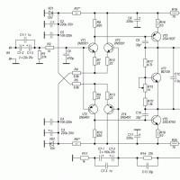
Let's review the origins: biquadrat is considered a subspecies of frame antennas, which primarily belong to the zigzag family. Kharchenko Kharchenko was the first to propose the Kharchenko antenna. In 1961 to catch television broadcasts. It is known for certain: at a frequency of 14 MHz, placing the biquadrat in the meadow, an ardent enthusiast managed to reach America. Not a bad result. We believe that the matter concerns refraction, plus diffraction plays out against the Earth. The HF range and below are used due to the ability of waves to refract, bend around obstacles, and it is possible to establish communication over a long distance. Let's go in order. Let's take a closer look at how to make a Kharchenko antenna with your own hands.
Antenna Kharchenko, “eight”, which today catches WiFi, cellular 3G. When installing outdoors, protect the product with a plastic casing.
Communications and antennas Kharchenko
Later it will become obvious: the design of the original Kharchenko antenna, to put it mildly, differs from what is being viewed on the network today. It’s not that they like, as Mayakovsky used to say, to delve into prehistoric g..., but the basics of the theory must be studied in order to avoid mistakes, to know the features of the structure. We are going to tell you how to make a Kharchenko antenna yourself. The author of the monograph avoids giving instructions on the choice of wire thickness, saying: reducing the diameter negatively affects the range. Kharchenko’s homemade antenna is capable of covering digital television in the 470 - 900 MHz spectrum. The characteristics of the device are amazing, the coordination is not very difficult. We'll tell you how to make a Kharchenko antenna, avoiding delving into theory. We recommend that miners study the original thematic edition of the author.
The length of the 14 MHz biquad wire is approximately 21 meters. This is how much cable field you will need to make a simple device. The device is powered by a television coaxial wire (impedance 75 Ohms). Eyewitnesses are sure: Kharchenko’s antenna does not require tuning. The authors are inclined to consider the latter a small (giant size) exaggeration. Think about it! You can plow through the natural landscape by covering your back with two coils of wire:
- skein of vole;
- coil of coaxial television cable.
Then deploy the antenna, the range of which is simply amazing. Polarization depends on which side the figure eight is turned. Let's reluctantly place the number icon, as the number symbol is written in arithmetic textbooks - we will begin to receive television, tilt it to one side, forming infinity - radio broadcasting will begin to be picked up. Since the vole bends well and bends back: if we don’t like one channel, we can quickly orient the antenna to another. The problem is disgusting: the excess wire, which is unnecessary for useful needs, will have to be either cut off or coiled, placed in such a way that it does not interfere with reception. And this is not such a trivial task as it seems to the first person you meet:
- if you put it horizontally, it will pick up television;
- if you stretch it to the ground, the intermediate wire will begin to take on vertical polarization;
- hang it on a branch - vertical polarization will be caught.

Kharchenko antenna design
We are probably used to seeing the same thing in the pictures. Here is how it is proposed to design a Kharchenko antenna (the VashTekhnik portal keeps pace):
- It is necessary to find out the wave frequency and polarization. The Kharchenko antenna is linear.
- The copper antenna is formed by two squares. Both stand on the corners, one touching. For horizontal polarization, the figure eight stands upright; vertical - lies on its side.
- The side of a square is found by the formula: wavelength divided by four.
- You can imagine the design if you imagine an oval, pulled together in the center across the larger side. The sides do not touch, although they are close to each other.
- The power cable is connected to the points where the sides approach. It is necessary to block one direction of the diagram - place a flat copper screen at a distance of 0.175 operating wavelengths, and place it on the braid of the power cable. The reflector is made of a metal plate. In the old days, they used textolite boards covered with copper.
Completed brief design of the Kharchenko antenna. The details become full of problems: the task is to strengthen the emitter. For the communication range - wire stretchers; television - a wooden frame is often used, studded with crossbars (resembling a cross); in the microwave range, modem owners support the emitter with a pair of plastic stands that pierce the screen. What does Kharchenko think about design concepts? The obedient slaves of the VashTekhnik portal took the trouble to get a book by an engineer, the text outlines the invention, a mountain of interesting things is written:


The geometric dimensions have been indicated, we list them together:
- The height of the square standing on the corner is 0.28 of the maximum wavelength, along the middle contour of the three.
- The distance between the outer frames across the direction of the wire is 0.033 of the maximum wavelength.
- The length of the matching line with a characteristic impedance of 100 Ohms is 0.052 or 0.139 of the maximum wavelength.
What else would I like to note about the original design... In order not to disturb the field of the Kharchenko antenna, the power cable comes from below, winds along one side of the frame, and enters the center. The mains don't go along the mast! Modern designs imply the presence of a screen. Therefore, the wire comes from somewhere behind, pierces the copper screen, and is connected in the right place to the figure eight. By the way, it is not at all necessary that the antenna consist of squares. The characteristics of the device do not depend greatly on the apex angle. The height of the figure eight (standing upright) must be maintained. Therefore, if the angle changes from 90 to 120 degrees, the sides lengthen. Proportional. Specific values can be calculated.
Now readers know how to make a Kharchenko antenna with your own hands. And here's another thing. I have seen, while surfing the net, structures where the emitter curved around the screen. In this way, the main lobe of the radiation pattern supposedly expands. In practice, in this case it is easier to use a patch. Here the platforms can be directed in different directions.
Again my exit. I have to keep the customers busy with the technical part of the project while the manager is on the phone.
The best alternative to the wave channel antenna for your operating conditions is the Kharchenko antenna. Don’t look at how simple it is, in fact it’s two antennas in one bottle, sorry, in a reflector, and this gives a gain of as much as three decibels. Durable, reliable, small-sized, indestructible design, easy to use. The not-too-sharp directional pattern ensures good penetration of radio waves over rough terrain even in bad weather, hence the mobility of the antenna, which does not require high lifting from the ground, which allows you to quickly put the equipment into operation in the field. The wide operating range of the antenna makes it universal. Preference should be given to horizontal polarization, since for a forest area there will be less loss in the passage of radio waves. (No, I shouldn’t have started talking about polarization; now I’ll probably fall asleep myself).
Photo 1 shows two Russian-made Kharchenko antennas. The large antenna is narrowband - for the 433 MHz range. The upper antenna is broadband - for the range 900 - 1800 MHz.
 |
| Photo 2. Two-story double circle. |
For my dacha, I made a similar antenna out of plastic, so in bad weather only digital television can reach me, and the antenna itself stands under a soft roof transparent to radio waves so that they don’t jinx it and don’t ask unnecessary questions. Three multiplex packages, two sports channels, two cartoons to catch my breath from the grandchildren and all this in excellent quality, I don’t tell anyone about this, otherwise in the rain they will come to my place to watch the football, where I will seat everyone.
It all started with the fact that I assembled a homemade transformable antenna "wave channel". It was just interesting to find out how, at extreme reception distances, its elements affect the quality of the signal in the decimeter range. In principle, the antenna suited me, but as a drawback it showed itself to be narrowband, excellently receiving digital packets densely spaced in frequency in my region, and the level of digital reception increased slightly in the absence of director elements. That’s when I had the desire to make a simple universal antenna for the entire decimeter wavelength range of television broadcasting, since all TV channels occupying the meter wavelength range had already been transferred to it in digital format.
 |
| Rice. 1. |
 |
| Fig.2. |
I had already begun to assemble a two-story “wave channel” antenna (Fig. 1) for two bands, but having simplified everything beyond recognition, (Fig. 2) I thus came to the antenna "Kharchenko" Another popular name is two-story double square or double zigzag. From a metal-plastic tube (metal-plastic for short), the antenna I assembled looks more like a two-story double circle or a pair of figure eights. Whatever you say, flexible aluminum tubes with a diameter of 16 mm covered with plastic make better circles than squares, and this geometric figure is the most optimal for radio waves.
It is better to remember the number 8, it is this position of the antenna that has horizontal polarization, that is, it coincides with the polarization of the antennas of television transmitters. Again, this figure is its amplification, expressed in decibels.
Antenna design.
Metal-plastic tube 2 meters long, 16mm in diameter.
I divided a metal-plastic tube 2 meters long (metal-plastic will be cut in multiples of meters when selling) into four parts, each 0.5 meters, and bent it from segments of a circle. Thus, each circle has a length approximately equal to the wavelength. I flattened the ends of each tube and cleaned the edges of plastic, making holes in them for joint fastening.
Coaxial cableRG 59/U or RK 75- 3.7-35 m 7 meters long.
The distance is taken for a convenient location of the antenna in the attic, under a soft roof transparent to radio waves. The minimum cable length can be 1 - 1.5 meters, if the antenna is located near the TV. To reduce the reverse passage of high-frequency currents through the braid of the coaxial cable, I passed it through a hole in the tube at the point of zero potential. Zero potentials are the top and bottom of the figure eight; they are used to attach the supply loop to the reflector. To make an outdoor antenna, the zero potential points must have electrical contact with the reflector, which is subsequently grounded for lightning protection.
Reflector.
The reflector itself does not have to be made in the form of circles, as I did, pursuing the goal of reducing windage, that is, reducing the swing of the pole from the wind in the case of using an external structure. It can be made from a metal mesh, a sheet of metal, or, if the antenna is used indoors, from foil glued to plastic or cardboard. I secured the edges of the reflector rings, stripped of plastic, with an aluminum plate.
Loop vibrator.
It consists of two tightened circles of metal-plastic and having a common electrical contact. To wire the cable, a contact pad made of double-sided fiberglass 1 mm thick is used. The platform ensures rigidity of the structure, and to ensure a lower SWR value in the operating frequency range and better matching, it was necessary to reduce the gap between the rings, thus increasing the capacitance between them. I had to make a double-sided print cut 1 mm wide with an offset.
It turned out that the contact pad for attaching the cable is a homemade capacitor, which provides better matching over the entire range from 490 to 900 MHz.
The distance between the figures of eight or between the loop and the screen ranges from 0.15 to 0.22 of the wavelength. This distance can be selected during the setup process based on the receiver signal level. The distance in the fixing strips between the centers of the circles is 13 cm.
 |
| Rice. 5. Antenna operating range. |
The most interesting point is to check the operation of the antenna and compare it with existing designs and determine which antenna is better.
So which antenna should you choose?
To answer the question I had to conduct
another casting.
 |
| Photo 10. Antenna competition. |
At the same time, in the same place, I connected antennas with the same number of elements in turn and recorded the signal levels of three multiplex packages, selecting one channel in each, and then calculated the average value for each antenna. The Olympus 2014 antenna and the two-story double circle differ from each other in the gain level of 0.3 percent, I repeat 0.3 percent. Taking into account the measurement errors, I compared the results and awarded first place to both antennas for technical performance. In last place, a purchased antenna with an amplifier very similar to the Kharchenko antenna (the one in the center in photo 10) greatly discredited itself, since it did not work both in the city and at the maximum distance from it, receiving only one multiplex package with a hang. .
 |
| Photo 11. First place. |
In terms of artistry, the first place is occupied by the Kharchenko antenna or a two-story double circle. It turned out to be more compact, that is, it takes up less space and is convenient to hang under a roof transparent to radio waves or attach it to a metal mast with a reflector.
The antenna for receiving digital signals, designed and assembled by engineer Kharchenko, looks purely outwardly like an ordinary double square made of thick copper wire. With their open corners, these squares are combined into a common outline, and a television cable outlet is soldered to the area where they are joined (figure below).
Kharchenko's classic UHF antenna, made at home, in addition to two squares, contains a reflector made of conductive material (it allows you to increase the efficiency of directional reception).
If a number of conditions are met, such an antenna can be used to receive ultra-high frequencies of mobile channels in 3g format, in particular.
Antenna design features
Decimeter version
A design feature of the Kharchenko antenna is a fixed ratio between the perimeter of each of its two squares and the length of the received waves (they must be equal). To obtain the required induced field strength, it is also important to select the correct diameter of the frame wire.
Since broadcasting was previously focused on the meter range, receiving such a signal would require a wire with a diameter of about 12 cm. In this case, the zigzag antenna would be too bulky and inconvenient to use, and its dimensions would not allow it to be used at home.
Kharchenko’s zigzag antennas experienced their second birth at the time of the advent of broadcasting in the decimeter bands.
Additional Information. A zigzag antenna designed to receive a UHF signal must have fixed dimensions, which will be discussed in the following sections.
The characteristic impedance for which such home-made structures are calculated is usually about 50 Ohms. This indicator, however, agrees well with a typical coaxial line with a corresponding parameter of 50 (75) Ohms. To expand the bandwidth of the television signal, such an antenna was made not from a simple wire, but from a flat copper or aluminum bus, the individual parts of which were connected into a biquadrate using pre-selected aluminum rivets (photo below).

At the junctions of the copper strips, the UHF antenna was additionally soldered; in this case, the distance between the rivets was taken as its length. In cases where, in order to obtain reliable reception, it was necessary to use a standard antenna amplifier, the developers did without the second square (one was enough for reliable reception).
Execution in the DVB-T2 standard
Digital broadcasting, designated by the “dvb t2” standard, is carried out, as is known, at UHF frequencies corresponding to TV channels from 21 to 69, using the “multiplex” format. In many Russian cities, local television stations are gradually switching to the dvb TV broadcast format, which is causing some interest in ensuring its reliable reception.
In this regard, the user must know that a homemade design for T2 must have the same dimensions as a classic antenna for UHF digital broadcasting.
Important! Modern television receivers, which include an antenna for a digital signal, can weaken it if the transmitting station is close.
In special situations, when the transmitter for the T2 band is very close, when using the old frame design, you will either have to completely remove the second square (or screen), or choose a less sensitive amplifier.
The following solutions can be chosen as options for manufacturing a dcv structure:
- Make a completely new receiver for t2 with your own hands;
- Try to build a combined antenna containing an element in the form of a circle made of wire 55.5 cm long (see photo below);
- With its help it will be possible to receive all known formats (including 3g mobile communications).

In the case when you need to make a structure for receiving Internet signals, including Bluetooth, WiFi (3g, 4g) or mobile communication channels operating on ultra-short waves, the dimensions of such an antenna will be very miniature.
Due to the high frequency, the dimensions of the antenna for 3g will be limited to a length of 10 centimeters, and all possible varieties of a homemade product can be assembled using the same drawing.
Significant differences regarding all possible versions of a miniature antenna (for Bluetooth or for a cell phone) will appear only in the dimensions of the receiving structure itself.
Additional Information. If you need to calculate such an antenna, you can use an online calculator.
The calculation procedure in this case is determined by the method of using a specific network resource (these methods are widely represented on the network for both T2 and other TV signal formats).
Self-production
UHF antenna
After the calculations for the Kharchenko antenna for the TV have been made, you can proceed to making it yourself.
In order to make a high-quality antenna, you will definitely need the following material and tools:
- Thick single-core wire (it’s better if it’s copper);
- An electric soldering iron, regular pliers, as well as a ruler and quick-setting glue;
- A piece of cable with Rwave equal to 50 Ohms;
- Foil fiberglass, an old DVD (CD) disc and/or, as a last resort, a can of sprat (they are needed to make a reflective screen for a zigzag antenna).
And finally, you should make a special spacer stand that sets the required distance between the antenna bus and the screen (a plastic bottle cap can be used as such a spacer).
The entire procedure for making an antenna with your own hands is best divided into a number of stages, namely:
- First you need to remove the protective insulation from the copper wire;
- Then, using a ruler, clearly mark the locations of future bends of the TV antenna;
- After this, using pliers, bend the wire in the previously marked places;
Note! The more accurately the wire is marked and the bends are neater, the better the digital television antenna will receive the signal.
- Upon completion of the frame molding, the antenna cable connection areas are carefully tinned using a soldering iron;
- Then the supply wire is soldered to the tinned area, but first a stand and a protective screen are successively strung onto a piece of cable;
- At the final stage of assembly, the entire resulting structure is glued with standard silicone (see figure below).

Improving WiFi and Bluetooth quality
It is known that the WiFi signal is transmitted, like other types of terrestrial communications, over a radio channel, which allows the use of an antenna design to improve the reception of a router or similar devices. According to a number of craftsmen from among the developers of 3g antennas, if in the design discussed above a parabolic dish is taken as a screen, the gain at WiFi frequencies can be increased to 31 dB.
Additional Information. Such a screen can be made from a tin can bent in a certain way.
When making a reflector for 3g or WiFi, the curvature of its surface is usually selected experimentally. To do this, a program must be installed on the transmitting/receiving device (router, for example) that can record the level of the signal entering the device.
Using such a program, it will be possible, by changing the curvature of the surface of a homemade screen, to monitor all changes in the gain (in real time).
Calculation technology
The calculation of parameters in this case is focused on the operating frequency of 2445 MHz (see photo).

Note that to calculate such an antenna you will need to know its following characteristic dimensions:
- Diameter of copper flat wire – 2.5 mm;
- Volume of stock of all material (wire 256.6 mm long);
- L1 – the outer side of one square, equal to approximately 30.8 mm;
- L2 – its inner side (29.6 mm);
- L3 – working frame length (84 mm);
- L4 – its effective width (43 mm).
In addition, you will need to calculate a characteristic parameter such as L5 (it is called the connection gap), which is usually chosen to be 1.9 mm. Let's add to this the height of the additional racks D - 13.6 mm, as well as the width of the screen B - 122 mm and, finally, its working length H - 122 mm.
Important! The reception of an antenna for a router or mobile format will be more confident the more accurately all the above dimensions are maintained.
The screen can be made from a small piece of foil fiberglass left over from old boards. In order to increase mechanical strength, it is additionally soldered to the braid of the signal output cable. As a screen, it is customary to use an old CD with a thin layer of foil, on which useful information is usually recorded.
In this case, to assemble an antenna for digital TV, you can use an old box from unwanted CDs.
Good specialists will calculate the data using their own experience and homework. But non-specialists will have to resort to the help of online calculators or their analogues widely available on the open network.
In the final part of the review, dedicated to how to make a Kharchenko antenna yourself, we note the following important points of this enterprise. Before starting to manufacture it yourself, the main thing is to correctly take into account all its characteristic parameters and indicators (including reception of the 3g format and a number of other ultra-high-frequency signals).
Only under this condition, with the help of such a relatively simple homemade product, it is possible to receive a UHF signal at a decent distance from the television center (at distances of up to 2 kilometers).
Video