Reading electrical drawings. Rules for reading electrical diagrams and drawings. Types and types of electrical circuits, coding
For novice electronics engineers, it is important to understand how parts work, how they are drawn on a diagram, and how to understand an electrical circuit diagram. To do this, you first need to become familiar with the operating principle of the elements, and in this article I will tell you how to read electronic circuits using examples of popular devices for beginners.
Diagram of a table lamp and LED flashlight
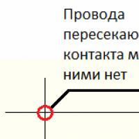
A diagram is a drawing in which the details of the circuit are depicted using certain symbols, and their connections are depicted with lines. Moreover, if the lines intersect, then there is no contact between these conductors, and if there is a point at the intersection, this is a junction of several conductors.
In addition to icons and lines, the diagram shows letter designations. All designations are standardized, each country has its own standards, for example in Russia they adhere to the GOST 2.710-81 standard.

Let's start studying with the simplest thing - the diagram of a table lamp.

Schematics are not always read from left to right and top to bottom, it is better to go from the power source. What can we learn from the diagram, look at the right side of it. ~ means AC power.
Next to it is written “220” - a voltage of 220 V. X1 and X2 - are supposed to be connected to an outlet using a plug. SW1 - this is how a key, toggle switch or button is depicted in an open state. L - conventional image of an incandescent light bulb.
Brief conclusions:
The diagram shows a device that is connected to a 220 V AC network using a plug into a socket or other plug-in connections. It is possible to turn it off using a switch or button. Needed to power an incandescent lamp.
It seems obvious at first glance, but a specialist must be able to draw such conclusions by looking at the diagram without explanation; this skill will make it possible to diagnose a malfunction and eliminate it, or assemble devices from scratch.
Let's move on to the next diagram. This is a battery-powered flashlight with an emitter installed in it.

Take a look at the diagram, perhaps you will see new images for yourself. The power source is shown on the right, this is what a battery or accumulator looks like, the long terminal is plus another name - Cathode, the short one is minus or Anode. For an LED, a plus is connected to the anode (the triangular part of the designation), and a minus is connected to the cathode (looks like a strip on the UGO).
It is necessary to remember that for power sources and consumers the names of the electrodes are reversed. Two arrows emanating from the LED let you know that this device EMMITS light; if the arrows were pointing at it on the contrary, it would be a photodetector. Diodes have the letter designation VDx, where x is the serial number.
Important:
The parts in the diagrams are numbered in columns from top to bottom, from left to right.
If you add a stabilization unit built to the circuit, the voltage of the power supply will be stabilized. In this case, only from an increase in the supply voltage, with drawdowns lower than Ustabilization, the voltage will pulsate in time with the drawdowns. VD1 is a zener diode, they are switched on in reverse bias (cathode to a point with positive potential). They differ in the magnitude of the stabilization current (Istab) and stabilization voltage (Ustab).

Brief summary:
What can we understand from this diagram? What . It is connected by the primary side (input) to an alternating current network with a voltage of 220 Volts. At its output it has two detachable connections - “+” and “-” and a voltage of 12 V, unstabilized.

Let's move on to even more complex circuits and get acquainted with other elements of electrical circuits.
Astana-2005
MINISTRY OF AGRICULTURE OF THE REPUBLIC OF KAZAKHSTAN
KAZAKH STATE AGROTECHNICAL UNIVERSITY
THEM. S. SEIFULLINA
Sorokin V.G., Nogai A.S., Ansabekova G.N.,
TUTORIAL
« Techniques for constructing and reading electrical diagrams»
for energy specialties: 2102, 2104, 2105.
Astana - 2005
Reviewed and approved “I approve”
For publication at a meeting of the educational
State Agrotechnical University named after. S.Seifullina
University named after S. Seifullina __________ _______________
Protocol No. __from______________ (Signature) (Full name)
“___” ____________ 2005
Sorokin V.G. – Associate Professor, Head Department of Electric Power and Management Kaz ATK
Nogai A.S. Professor of the Department of Electrical Supply.
Ansabekova G.N. - senior Lecturer at the Department of Electrical Supply
The textbook is compiled in accordance with the requirements of the curriculum and the temporary standard curriculum for the discipline “Electrical Engineering Drawings” and includes all the necessary information for mastering this course.
The textbook is intended for students in specialties 2102, 2104, 2105 in Russian.
Reviewers:: Pyastolova I.A., Ph.D., Associate Professor of the Department of Operation of Electrical Equipment, Kazakh State Agrotechnical University named after. S. Seifullina
Nurakhmetov T.N.., Professor, Department of Radio Electronics, Eurasian National University. L. Gumileva
Reviewed and approved at a meeting of the Electrical Supply Department.
Protocol No._ 2_ __ from “_ 30_ _ “__09_ _______2005
Reviewed and approved by the methodological commission of the Faculty of Energy.
Protocol No. _3___ from “_ 16 __ “__10_ _____2005
© Kazakh State Agrotechnical University named after. S. Seifullina
Introduction
In modern conditions, the saturation of all sectors of the national economy and everyday life (regardless of forms of ownership) with electrical products, installations, instruments, communications, computers and even electrical toys, the requirements for the rules for their clear, unified outline and reading of all types of electrical drawings have increased significantly. It must be said that modern electrical installations are so complex that it is almost impossible to manufacture, operate, or repair them “from memory” without a drawing. Such drawings are electrical diagrams.
If a drawing, called the language of technology, is an international means of transmitting technical information, then the conventional graphic and letter symbols approved by the interstate standard are the international alphabet of the language of drawings.
Design (project) documents are divided into graphic (drawings and diagrams) and text (explanatory notes, calculations, technical specifications, etc.)
Of course, the development of such documentation is carried out by experienced electrical specialists.
In the process of studying in this discipline in the first year and coursework and diploma design in subsequent courses, the student acquires practical skills, accumulates reference material on elements, assemblies and blocks of electrical products, learns to freely read electrical circuits and automation circuits, and also use it in practical activities.
The basics of this knowledge are necessary for all technical specialties and specializations of engineering faculties.
The purpose of this textbook is to systematize the basics of knowledge in electrical disciplines, teach the rules of electrical drawing, acquire initial reference material, and also master the basics of reading electrical circuits and automation circuits.
General information
During scientific, design development and design work, as well as during setup, installation, operation and repair of electrical installations and electrification projects, the main unified regulatory document is electrical circuits, which are regulated by international and state standards, most often included in the “Unified System of Design Documentation” ( ESKD) GOST 2721-74, 2752-74, 2755-87. For example, GOST 2702-75, Rules for the execution of electrical circuits.
In accordance with state and international standards main types and types circuits used in electrification projects and electrical products in accordance with GOST 2701-84 are numbered with appropriate codes consisting of letters and numbers (see Table 1), which are stamped in the drawing.
Table 1. Main types and types of circuits used in electrification projects
For example, in the stamps of the drawings of a coursework or diploma project “Electrical circuit diagram”, it is encrypted ABVG.ХХХХХХ 25/Э3, and the connection diagram of automatic devices, of which there are several types in the complex, is encrypted as ABVG.ХХХХХХ 253 A4.2 A4, etc.
Electrical circuits are made on sheets (formats) of the following sizes: A0-841*1189; A1-594*841; A2-420*594; A3-297*420; A4-210*297-GOST 2.301-68
Electrical circuits are developed and supplied for use, usually as a complete set. For example: - standard set: structural, functional, circuit and wiring diagrams.
Taken together, electrical diagrams must contain sufficient information for the design, manufacture, installation, configuration, operation and repair of the product and at the same time must be rational, compact and easy to read. Therefore, it is necessary to understand their meaning (wording), know drawing techniques and the rules for reading them. Key terms and definitions are given in Table 2.
Table 2. Terms and definitions
Types of electrical circuits
Structural diagrams
The structural diagram defines the main functional parts of the product, their purpose and relationships (for example, see Fig. 1.1).
The functional parts in the diagram are depicted as rectangles.
The graphical construction of the diagram should give the most visual representation of the sequence of interaction of functional parts in the product, for which purpose the name of the functions is indicated in each part and explanatory (indicative) inscriptions and parameters are made.
|
|
|
|
|
|
|

Functional diagrams
The functional diagram explains certain processes of control functioning, both electrical and technological, occurring in the system and device as a whole, and in individual parts and elements.
These diagrams will be discussed in more detail as functional and technological automation diagrams in Part 2 of the book.
Schematic diagrams
Schematic (complete) diagram - a diagram that defines the complete composition of elements, nodes and connections between them, as well as the elements with which input and output circuits begin and end (connectors, clamps, terminals, etc.) and gives a detailed idea of the principles of operation products (installations).
The basic requirements of the standards for the rules for implementing circuit diagrams are enshrined in GOST 2.710-81, GOST 2.755-87, GOST 2.721-74, GOST 34.201-89, GOST 21.403-80.
Schemes are drawn for devices, apparatus and systems that are in a disconnected (de-energized) state.
The reference graphic material of electrical circuits, as a rule, does not correspond to the scale and general appearance of the element, and therefore the standards introduce requirements for drawing elements in the form of conventional graphic images and applying conventional alphanumeric designations, which naturally introduces certain difficulties in the study.
In order to read diagrams meaningfully, you need to understand what is depicted on it. To do this, you should: know the terminology and understand the system for constructing graphic and alphanumeric symbols of circuit elements; know in what cases one or another designation is used.
Conventional graphic symbols are formed from the simplest geometric shapes: squares, rectangles, circles, as well as from solid and dashed lines and dots. Their combination according to the system provided by the standard makes it possible to easily depict everything that is required: apparatus, instruments, electrical machines, mechanical and electrical communication lines, types of winding connections, type of current, nature and methods of regulation, etc.
To construct conventional graphic symbols means to provide a special sign for each element, but then tens of thousands of complex symbols would be required. Since new elements and devices appear every day, new connection methods and it would be impossible to provide designations in advance for all cases. The symbols would be difficult both to depict and to read.
To simplify the image and reading, standards and rules allow fairly clear fragments in diagrams to be drawn without detail (blocks, harnesses, connectors, logical elements, etc.), or to use additional generally accepted images.
The following reference material is offered for study and use in the educational process: conventional letter symbols and conventional graphic images.
Conventionally, alphabetic and digital designations in electrical circuits are assigned to all elements, devices and functional groups in the form of one-letter and two-letter codes with numbers GOST 2.710-81 (it is recommended to use two-letter codes).
Alphanumeric designations are intended for recording information about elements and devices in code, either printed on drawings, or used as information in text documents.
In electrical circuits, the positional designation of an element consists of three parts that have an independent semantic meaning and are written without separating marks and spaces (letters of the Latin alphabet), see table. 3
In the first part, one letter (one-letter code) or several letters (two-letter code) indicate the type of elements, for example, R-resistor, PA-ammeter.
In the second part, indicate the number of the element among similar ones (R1, R1, C1, C2, HL1, HL2, etc.). It is allowed to add the conventional number of the depicted part of the device through a dot to the device number (for example, KV1.5 is the fifth contact of the KV1 relay). However, usually when making schematic electrical diagrams, including the separated method of execution, various elements of the same type, for example, contacts of one device (relay, etc.), are not assigned special positional designations; they have the same designation as the device to which they belong. So, all KV relay contacts will have the position designation KV1. The first and second parts of the designation are mandatory.
The third part indicates the functional purpose of the elements (R1F-resistor R1, used as a protective one).
Two-letter codes to indicate the functional purpose of the elements are given in Table 3.
Table 3. Position designation of circuit elements (letter codes)
| Examples of element types | Code |
| Measuring instruments: | P |
| Ammeter | PA |
| Active energy meter | P.I. |
| Reactive energy meter | PK |
| Ohmmeter | PR |
| Recording device: | PS |
| Voltmeter | PV |
| Wattmeter | PW |
| Switches and disconnectors in power circuits: | Q |
| Automatic switch | QF |
| Short circuit | QK |
| Disconnector (limit switch) | QS |
| Transformers, autotransformers: | T |
| Current transformer | T.A. |
| Electromagnetic stabilizer | T.S. |
| Voltage transformer | TV |
| Capacitors | C |
| Generators, power supplies: | G |
| Battery | G.B. |
| Engines | M |
| Inductors, chokes, reactors | L |
| Arresters, Fuses, protection devices: | F |
| Discrete instantaneous current protection element | F.A. |
| Discrete inertial current protection element | FP |
| fuse | F.U. |
| Discrete voltage protection element, arrester | F.V. |
| Various elements: | E |
| A heating element | E.K. |
| Lighting lamp | EL |
| Relays, contactors, starters: | K |
| Current relay | K.A. |
| Indicator relay | KH |
| Electrothermal relay | KK |
| Contactor, magnetic starter | K.M. |
| Time relay | KT |
| Voltage relay | KV |
| Device (amplifier, unit, devices) | A.A. |
| Converters of non-electric quantities into electricity | B.A. |
| Display device | M.A. |
| Integrated circuits: analog, digital | DA,DD |
| Transistors | VT |
| Diodes | VD |
| Thyristor | VS |
| Switch-switch | S.A. |
| Push-button switch | S.B. |
If necessary, sections of electrical circuits are marked on the diagram to identify sections of circuits, and may reflect their functional purpose in the diagram. Sections of the circuit separated by breaking or closing contacts of devices, relay windings, resistors and other elements have different markings. Sections of the circuit separated by detachable or permanent contact connections must have the same markings. To identify differences in sections of circuits, it is allowed to add numbers or other designations to the markings, for example, 75-4 (section 4 belongs to the control circuit of engines 75).
The markings are affixed sequentially from the input of the load power source, and the branching sections of the circuit are placed from top to bottom and from left to right. AC power circuits are marked with letters indicating phases and sequential numbers (A, B, C, A1, B1, C1, etc.).
Input output DC power circuits are marked with polarity: plus “+”, minus “-”. Sections of circuits with positive polarity are marked with even numbers, and sections of negative polarity with odd numbers. Control circuits (starting and stopping electric motors, alarms, protection, blocking, measurement) are marked with sequential Arabic numerals.
The sequence of numbers can be set within the functional circuit. Marking can be done with numbers taking into account the functional characteristics of the circuits, which makes the circuit easier to read, for example:
Measuring, control, regulation circuits……………….from 1 to 399
Signaling circuits……………………………………………………….from 400 to 799
Power circuits……………………………………………………………...from 800 to 999
The marking (number) is placed near the ends or in the middle of the chain section (if the chain is vertical, to the left of the image of the chain section, if horizontal, above the image of the section).
For additional information about the principle of operation of components and individual devices, the circuit diagram is supplemented with tables, notes, and cyclograms. Table 4 can serve as an illustration of such information.
Table 4. Cyclogram.
| Contact | Time in minutes | Contact assignment | ||||||||||||
| K1 | CEP motor control | |||||||||||||
| K2 | Stirrer control | |||||||||||||
| K3 | Fan control | |||||||||||||
| K4 | Valve 1 control | |||||||||||||
| K5 | Valve control 2 | |||||||||||||
| K6 | Valve control 3 |
Conventionally graphic images elements are made in lines with a thickness of 0.2 to 1 mm. (depending on sheet format and functional significance). So, for example, for general power circuits you can use lines 1 mm thick, for power circuits of individual consumers - up to 0.6 mm thick, for control circuits - 0.2-0.4 mm thick. Conventionally, graphic images of the main elements are shown in Table 5.
Table 5. Conventionally graphic images of electrical circuits
| Name | Conditional image |
| Designation for general use | |
| Separate wire | |
| Crossing of wires, communication lines A) without connection B) with electrical connection | A) B) |
| Cable, harness |  |
| Screened line | |
| Electrical signal direction | |
| Mechanical link | |
| Current-collecting mobile device for EPS A) general designation B) controlled noitograph | A) B) |
| Acceptable image of circuits of three-phase symmetrical systems (single-line image) | |
| A) grounding B) housing | A) B)  |
| Contact A) dismountable B) permanent connection C) plug connector | A) B) C) |
| Electric cars | |
| Electric machine A) general designation B) with the designation of the rotor and stator (single-line image) | A) B) |
| Asynchronous machine with wound rotor | |
| Two-phase asynchronous machine | |
| DC machine | |
| DC machine with mixed excitation | |
| Inductors, chokes, transformers | |
| Winding of inductor, inductor, transformer | |
| Inductor with ferromagnetic core | |
| Reactor |  |
| Single-phase transformer with ferromagnetic core A) main image B) acceptable image | A) B) |
| Three-phase transformer A) general designation B) three-winding | A)  or in) or in)  |
| Autotransformer A) three-phase B) single-phase | |
| Measuring current transformer | |
| Voltage transformer A) single-phase B) three-phase | A) B) |
| Core (magnetic core) A) ferromagnetic B) diamagnetic | A) B) |
| Switching and contact devices | |
| High voltage power switch | |
| High voltage disconnector | |
| Short circuit | |
| Coil of relay, contactor and magnetic starter A) general designation B) thermal relay | A)  IN) IN) |
| Switching device contact A) making contact B) opening contact | A) B) |
| Plug socket A) open wiring B) closed wiring | A) B) |
| Contact with mechanical connection (limit switch, pressure switch) |   |
| Thermal relay contact | |
| Three-pole switch A) without automatic return B) with automatic return | A) B) |
| Normally closed contact with retarder (time relay contact) A) when triggered B) when returned | A) B) |
| Contact A) switching B) with middle position | A) B) |
| Power circuit contact | |
| Push-button switches A) normally open contact B) normally closed contact | A) |
| Contact of electrothermal relay (with spaced method) | |
| Switch single-pole, three-position (bar) | |
| Switches with complex switching |  |
| Resistors, capacitors | |
| Resistor is constant | |
| Variable resistor a) parametric c) potentiometer c) rheostat d) subscript e) thermistor | A) B) C) D) E) |
| Electric heater | |
| Constant capacitor A) general image B) polar C) electrolytic | A) B) C) |
| Arrester |  |
| fuse | |
| Devices | |
| Device A) integrating (electric energy meter) B) recording | A) B)  |
| Electrical measuring device (for example, ammeter) | |
| Signaling equipment | |
| Incandescent lamp A) lighting and signal lamp B) lamp | A) B) |
| Gas-filled indicators A) low pressure lamp B) gas-discharge sign indicator |  |
| Secondary power sources and their elements | |
| Type of current and purpose A) constant B) single-phase alternating C) three-phase alternating industrial frequency D) alternating high frequency | A) B) C) D) |
| Galvanic or battery cell | or |
| power unit | |
| Bridge diode connection diagrams A) single-phase B) three-phase | A)  IN) IN) |
| Zener diodes a) single-sided b) double-sided | A) B) |
| Elements of electronic circuits | |
| A) diode B) thyristor C) LED D) optocoupler | A) B) C) D) |
| Transistors type A) p-p-p b) p-p-p | A)  B) B)  |
| Unijunction transistor |  |
| Unipolar field effect transistors A) p-channel B) p-channel | A)  B) B) |
| MIS - transistor |  |
| Elements of integrated electronic technology | |
| Basic element | |
| Logic circuits A) repeater B) inverter (NOT) C) addition (OR) D) multiplication (AND) | A) B) C) D) |
| Bipolar cell (trigger) | |
| Decoder | |
| Digital counter | |
| Operational amplifier |
Almost any basic electrical circuit is built on the basis of elementary circuits and standard components. This greatly simplifies the development, construction and reading of circuits of any complexity.
It is recommended to depict individual circuits of basic electrical circuits with horizontal (vertical) lines (rows) in a sequence from top to bottom (from left to right), determined by the order of connections and operation of the elements installed in them. This method of executing circuits is called line-by-line. To make it easier to find elements on the diagram, the lines are numbered: 1,2,3,4, etc. (see Fig. 2)
Switching devices (contacts, relays, push-button switches, etc.) on diagrams, as a rule, should be depicted in a position corresponding to the absence of current in all circuit circuits and external forced forces. If the diagram adopts other provisions for such devices, this should be specified in the note. Contacts of signaling and control devices are depicted with a rational value of their parameters.
Fig 1.2 Example of designation of line chains.

If the diagram is complex, to make it easier to read, explanatory notes should be given on the right side of the lines, for example: “Engine is on,” etc.
Devices on the diagrams can be depicted in a combined or separated manner (Fig. 3). With the combined method, the components of the devices (for example, the coil and contacts of relay K1) are depicted close to each other. With the spaced method, the components are placed in different places of the diagram so that the individual parts of the circuit are depicted more clearly. It is allowed to show some devices in the diagram in a spaced manner, and others (more structurally complex) - in a combined manner. It is also allowed (if the entire circuit is made in a spaced manner) on the free field of the sheet to give graphic designations of individual devices made in a combined way (Figure 1.3).


Figure 1.3. Schematic diagram of electric motor control:
a) – a combined method of depicting elements; b) – spaced-out method of depicting elements: A1 – contactor; A2 – push-button station; A3 – thermal protection relay; KM – magnetic starter: KK1, KK2 – thermal protection relay contacts (A3).
Thus, we became acquainted with the technique of drawing electrical installation diagrams (see Table 2). The complex of electrical installations for transport transmission, distribution (power supply) of electricity is called electrical networks. They have a complex of overhead and cable lines, substations, switchgears, conductors, etc. Electrical networks up to 1000V and over 1000V.
Substations provide transformation and distribution of electricity. For this purpose, technological electrical equipment is located on the territory of the substation, connected in accordance with the main electrical circuit diagram. An example of which is shown in Fig. 4.

Fig.4. Diagram of a 110 kV substation with separators and short circuiters.
Techniques for reading electrical diagrams
Reading a schematic diagram begins with determining the purpose of the device, the composition of its circuit (power part, control unit, protection, etc.) and familiarizing yourself with the list of elements, for which you find each of them on the diagram, read all the notes and explanations.
Wiring diagrams- these are drawings showing the actual location of components both inside and outside the object shown on the diagram. Such circuits are drawn for the installation of many types of radio equipment and not only, with the help of wiring diagrams, for example, electrical cabinets are assembled. The wiring diagram is a list of radio parts, assemblies and components, but they are not connected to each other by tracks; the route is indicated on the terminals of these elements. A route is an alphanumeric designation on the diagram, indicated on the terminals of the elements, indicating which other element this circuit should be connected to. All wiring diagrams read the same, but engineers may draw them differently. In this article we will learn how to read wiring diagrams and do installation; I will give all examples with electrical cabinets.
Wiring diagrams
When installing, it is convenient to work with two circuits, the installation circuit and the electrical circuit. The wiring diagram is drawn after drawing up the circuit diagram; some points may be missed when drawing up wiring diagrams; in this case, you can refer to the electrical diagram. Let's take a small piece of the circuit diagram and see how it should be read, how to correctly indicate the route, etc., for example, there is this piece of the wiring diagram:
The diagram shows 2 relays, what type they are and what voltage is usually indicated next to the relays, or written in the electrical diagram, i.e. If the wiring diagram does not say (or maybe you forgot to write) the operating voltage of any element, open the electrical diagram, find this element there and look. In this case, we depict 2 relays: KV8 and KV9, in circles, above the element the serial number or element number is indicated. And the circles inside are, as you probably already understood, the contact pads of the relays, if in another way, then the seats, contacts. The number is also written inside the circles, and in letters - A- And - IN- contacts for power supply are indicated.
Contacts that must be connected to other elements are carried out in strips beyond the edge of the case and a route is written on the edge; in our case, one contact with route -41B- departs from element -40-, this route indicates that contact number -B- of element number -40- must be connected to contact -B- of element -41-. We can say that contacts -B- of the relays -40- and -41- are connected together. As for the route instructions on cambrics, on element -40- a wire is screwed onto contact -B- (since we have relay contacts with screw terminals) on which the cambric is put on with the inscription -41:B-, and on element -41 - another cambric with route -40:B- is put on contact -B-.

To put it simply, cambrics (or cable markers) indicate return routes with connected elements.
On some elements, for example on the same relays, some radio elements may be drawn; below in the diagram, diodes are drawn parallel to the windings of the relays:

Such elements, as a rule, in the drawings will be connected directly to the contacts WITHOUT indicating the routes - why write a route when it is already clear that the anode of the diode -VD5- is connected to contact -B- of the relay -K4-, and the cathode is connected to contact -A- of the same element. Cambrics are NOT used for the output of such elements and the route accordingly is not written. If you look more closely, in diagram 2 you will see a so-called jumper that connects contacts -A- of elements -30- and -31- (relays -K4- and -K5-) to each other. Such jumpers are usually drawn in cases where it is easier to draw a line between elements, especially if they are located next to each other, than to write a route on the diagram. If the elements were located at different ends of the wiring diagram, then drawing a long line connecting these two elements would not make sense; it would be easier to indicate the route. I think, and here it is clear that contact -A- of element -30- is connected to contact -A- of element -31-. There is also a jumper on the diagram that connects contacts -11- and -A- of element -30- to each other. The jumpers usually do not indicate the route, both on the installation diagram and when installing this section, the diagram, but I still advise beginners not to be lazy and sign the cambrics.
The installation of the circuit can be carried out with different wires, for example, shielded, power, ordinary wiring, etc. or wires with different sections. On wiring diagrams, it is usually written on the edge which wires need to be used for installation and what their cross-section is, an example is below:

Below you can see a small section of such a diagram, which indicates which wire to use to install these circuits. From the diagram it can be seen that the installation of contacts 1,2,4 of connector X13 must be carried out with a wire with a cross-section of 0.35mm2, and the connection (installation) of contacts 9,15,16 is carried out with a wire of 0.75mm2, etc. By the way, grounding installation is carried out with a yellow-green wire, as is customary.

Typically, most elements on wiring diagrams are easy to read and understand, many elements (resistors, capacitors, diodes, light bulbs...) are designated in a standard way.

But often, on the assembly line they draw elements, after looking at which you don’t immediately understand what they are, in such cases we look at the serial number of the element and go look for it on the circuit diagram. Here, for example, is one of the options for designating screw terminal blocks - you must admit, you won’t immediately understand what it is.

Below is the designation on the wiring diagram of a three-phase transformer; the fact that this is possibly a transformer can be guessed by the inscriptions A, B, C (phases).

This is how a three-pole circuit breaker can be designated

By the way, they can be very different, there are circuit breakers for 10-20 amperes, and there are for high currents (1000A or more) with a magnetic drive, which electrically switches the circuit breaker, when triggered there is a strong crackling noise.
In general, difficulties arise only at first; if you get a job at some enterprise, consult with the employees or the engineer, the one who drew the installation.
Installation
The installer usually connects the parts in the cabinet body with wires. But some people’s responsibilities also include arranging elements inside the cabinet. We will only consider connecting the elements to each other with wires. Before you begin installation, figure out in your head how you will route the wiring harnesses inside the cabinet. Try not to lay a lot of bundles; if the wiring diagram contains elements that are connected to each other by a shielded wire, then the shielded wires must be laid separately, and the screens themselves must be connected to a common wire or ground. It is advisable to fasten the power wires after completing the main installation. Wires for installation are usually provided in coils or reels; they should be unwound carefully and there is no need to cut off several ends; for convenience, they are placed in special stands for easy unwinding; and also, do not throw away the plate that comes with the wire; the plate indicates the cross-section of the wire and some other parameters, if you lose it, next time it will be difficult to determine the parameters of the wire. The cambrics are needed to indicate the route, which are then placed on the ends of the wires. Indicating routes is necessary so as not to get confused in the wires yourself; there is no need to call them every time in case you forget which wire goes where. In addition, this makes troubleshooting and repairing the device easier.
Photo from the archive, this is what my workplace looked like:

Required Tools
Before starting installation, prepare the following tools:

Of course, something else may come in handy, but as a rule this is enough. Most importantly, start working in a good and cheerful mood to avoid mistakes - electronics don’t like jokes.
Before starting installation, carefully study the diagram; installation should begin from the area where the most elements are located; you should also pay attention to where the wires go. If a group of wires goes from one section to another section, you need to start from this place. If there are devices and buttons with regulators on the cabinet door, then installation begins with the door; a loop is made from the resulting wiring harness from the door to the cabinet body so that the door opens and closes normally.

Installation can be performed with different wires; the wiring diagram always indicates which wire should be used for a given section of the circuit; it is not recommended to do installation with a wire of a smaller cross-section than indicated in the wiring diagram, because a wire with a smaller cross-section may not withstand the required currents and may melt or become exposed. Never remove more insulation from a wire than is necessary; firstly, it is not beautiful, and secondly, it may accidentally short out if the wires are located next to each other. If the wires are attached, say, to relays or to terminal blocks using screws, estimate how deep the wire can go under the screw - that’s how much and remove the insulation. The terminals of wires from which the insulation has been removed and which are attached to elements in the cabinet must always be tinned! As soon as one end of the wire has been stripped and tinned, a cambric is taken, a route is written on it, after which it is put on the wire, and the wire itself must be soldered or screwed to the element. A cambric is also placed on the other end of the wire indicating the return route, then the end of the wire is tied into a knot and the wire can be thrown; we do not need this end of the wire yet. At the first stage of installation, cambrics are put on all other ends of the wires indicating the routes, the ends are tied in a knot so that the casing does not fly out and the wire is thrown. When you finish attaching the ends of the wires in a certain area, you will end up with a small braid of wires. Then this pigtail is carefully assembled and laid along the body (along the wall) of the cabinet, the wires are laid to the element where they should go according to the wiring diagram, i.e. from one element to another. As the laying progresses, the harness can branch and go to another element.

In the end, a bundle of wires with dressed cambrics at the ends should form. The figure above shows a bundle of wires near the terminal blocks; the wires are cut to the required length, the insulation is removed from them, tinned, and attached to the terminal blocks. And so on with all the wires that, according to the wiring diagram, should go to this element.
Of course, with the installation of simple household devices, such as power supplies or AF amplifiers, everything is much simpler. Typically, when connecting nodes or boards to each other with wires, you can specify power buses, input or output, plus or minus power, voltage, and so on as routes.
As soon as the main installation is completed, you can begin installing the power circuits; cambrics are put on the power wires in the same way and the route is written in the same way. More often, power wires are used for supply circuits and on cambrics, as a rule, only the phase is indicated.

After the installation is completely completed, they begin to test the circuits. DO NOT TURN ON THE DEVICE WITHOUT PRELIMINARY CHECKING AND CALLING! For dialing, it is convenient to use a multimeter with a tweeter. For example, in the diagram below, if we touch one probe of the multimeter to the contact of the resistor -4:1-, and the other probe to the contact of the light bulb indicating the route -23:R12- - the multimeter should beep, if it turns out that there is no contact, then the multimeter naturally will be silent.

In this case, you need to look for an error; perhaps you screwed one of the ends of the wire to another element, or it is quite possible that there is simply no mechanical contact, especially if the clamps are screw. Finding errors is a rather labor-intensive process; it is better to do everything correctly and without errors from the beginning; after installing a section of the chain, always recheck the chain. If after checking no errors were found, then you can slowly start launching. First, as a rule, they simply supply power, while the machines are turned off and the boards can be removed from the device, thus once again checking the correct installation and whether there is a short circuit anywhere. Afterwards, you can check the indication and starters by forced switching on, as well as other auxiliary elements of the circuit. Of course, different devices are configured and adjusted in different ways; it is impossible to give exact recommendations here. In general, my responsibilities only included installation of the circuit, and the configuration was already carried out by another specialist. During the first start-up of the device, touching the body and elements is strictly prohibited! Always turn off the power COMPLETELY before accessing the device.
Electrical diagrams are a graphical representation of components, mutual connections, connections of electrical devices, and installations. Diagrams help you see and understand how an electrical installation or device works. In case of repair, having a diagram makes troubleshooting and troubleshooting much easier. Wiring diagrams do not provide information about the operation of the device; they are intended for its assembly. The ability to read various electrical diagrams is important for both beginners and experienced specialists; it is necessary during assembly, installation and maintenance, and troubleshooting.
Types and types of electrical circuits, coding
In accordance with GOST 2.701-2008 “Unified system of design documentation (ESKD). Scheme. Types and types. General requirements for implementation" electrical circuits are assigned a type code designation with the letter "E".
The table shows the types of circuits regulated by GOST.
| Circuit type | Definition | Circuit type code |
| Structural | A document defining the main functional parts of the product, their purpose and relationships | 1 |
| Functional | A document explaining the processes occurring in individual functional circuits of the product (installation) or the product (installation) as a whole | 2 |
| Fundamental (full) | A document that defines the full composition of elements and the relationships between them and, as a rule, gives a complete (detailed) understanding of the principles of operation of the product (installation) | 3 |
| Connection diagram (installation) | A document showing the connections of the component parts of the product (installation) and defining the wires, harnesses, cables or pipelines by which these connections are made, as well as the places of their connections and input (connectors, boards, clamps, etc.) | 4 |
| Connections | Document showing external connections of the product | 5 |
| General | A document defining the components of the complex and their connections to each other at the site of operation | 6 |
| Locations | A document defining the relative location of the components of the product (installation), and, if necessary, also bundles (wires, cables), pipelines, optical fibers, etc. | 7 |
| United | A document containing elements of different types of circuits of the same type | 0 |
The drawing code consists of a letter, in our case it is the letter “E” and a digital part that determines the type, according to Table 1. For example, E1 is an electrical structural diagram, E5 is a diagram showing the external connections of the product.
Scheme standards according to GOST
You need to start by studying conventional graphic symbols (CGI). The designations on the drawings have a standard appearance and are regulated by GOSTs, for example, GOST 21.210-2014, GOST 2.755-87, GOST 2.721, GOST 2.756-76 and a number of others. Image standards apply to all elements, including connections between them, installation methods, laying, etc.
In some cases, GOST allows deviations from standards. For example, when drawing up structural combined diagrams, non-standard or close-to-real images of objects and photographs are often used, accompanying them with descriptions with brief explanations, as in the diagram of a telephone set.
But in general, they try to comply with the standards so as not to introduce discrepancies and confusion into the documentation, especially when it comes to serious projects for industrial enterprises.
Large images are divided into parts, indicating links to other sheets or indicating connections. The initial position of relay contacts, buttons, coils is shown in the absence of voltage, this is the standard.
Let's consider the above using the example of a basic relay circuit for controlling a conveyor.

There are two functional parts: a power part, consisting of motor power circuits, and a relay, which is designed to control the power part.
The power part consists of:
- Three-phase power lines 380V 50Hz, with a link to a set of “EM” drawings from where this power is supplied.
- Circuit breaker 2-QF.
- Contactor 2-KM.
- Thermal relay 2-KK.
- Electric motor 2W.
The phases are designated by the Latin letters A, B, C. Since three-phase power is used, the contacts of the circuit breaker and contactor are mechanically connected to simultaneously turn on/off all three phases.
The relay part contains:
- Automatic power switch 2-SF.
- SB buttons.
- Switch 2-SA.
- Time relay 2-KT.
- Relay 2-K1…2-K6.
- Power supply 24V 2-GB.
- Signal lamps 2-HL1… 2-HL4.
Connecting lines represent electrical connections between elements. The intersecting lines are not connected to each other. Alternatively, the lack of connection is indicated by an arc symbol. The presence of a connection is indicated by a point at the intersection or junction.
Contacts of relays, switches and other switching devices have two states:
- Normally open, when the contact is open without energizing the relay.
- Normally closed, when the contact is closed without energizing the relay.
Accordingly, when voltage is applied to the relay or contactor coil, the relay will be attracted and the state of the contacts will change to the opposite. The same thing will happen with the button and the circuit breaker; when it is turned on, the state of the contact changes.
Reading schematics
Depends on their construction and purpose of use. The flow of current in electrical circuits begins and ends at the power source. If this is a direct current source, then from plus to minus, if alternating, then from the phase wire to the neutral wire or between phases. You can start reading both from the power source and from the load. The power circuit from the source reads like this:
- When the 2-QF machine is turned on, the mains voltage is connected to the open contacts of the 2-KM contactor.
- If there is no overheating, the thermal relay contact 2-KK is closed.
- After the relay part has worked out, the 2-KM contactor coil is turned on.
- The 2-KM contactor is attracted and, through its contacts, supplies power to the 2-W electric motor through a thermal relay.
Diagrams are often read in reverse order when troubleshooting. For example, our engine does not turn on.
- We check the presence of voltage on the 2-W motor. There is no tension.
- We check the thermal relay 2-KK. The thermal relay is normal, its contacts are closed.
- We check whether the 2-KM contactor is turned on. The contactor is disconnected.
From there you can start looking for reasons for turning off the contactor. This can be either turning off the 2-QF machine, or turning off the 2-KM coil, which is turned on by a relay circuit. Thus, reading electrical drawings is similar to reading books, following the path of current flow from element to element.
The relay part looks somewhat more complicated, but if we look at it in parts and move sequentially, step by step, it is not difficult to understand the logic of its operation. Complex circuits always consist of several separate functional units. Having dealt with the individual fragments and connections between them, a complete picture of the operation of the entire circuit emerges.

For example, in this circuit there is a testing unit for light signaling. It consists of a 2-SB4 button and diodes connected to the HL signal lamps. The button is connected to the “+” of the 24V 2-GB power supply with a normally open contact. All lamps are permanently connected to the “-” power source. When the button is pressed, the circuit is closed through contact 2-SB4, diodes, lamps. As a result, all 4 lamps light up. In this way, their serviceability is visually determined. When the button is released, the circuit breaks and the lamps go out.
The sound alarm testing unit 2-HA1, 2-HA2 works in a similar way with the button 2-SB5. Even though these nodes are on the same drawing and connected to other parts, they are separately functioning complete circuits.
The main control circuit assembles the chains of the tape relay, emergency stop, readiness, and after a time delay determined by the 2-KT time relay, relay 2-K7 with its contact turns on the 2-KM power contactor, which starts the 2-W engine.
Knowledge of graphic symbols, like the alphabet for reading books, is the main condition for reading diagrams. But the alphabet alone is not enough for reading; you need to be able to connect letters into words, and words into meaning. Understanding the operation of a circuit diagram is impossible without understanding the operating principle of the devices from which it is assembled. So, if a person does not understand how an electromagnetic relay or timer works, he will not be able to understand what will happen when voltage is applied to one or another part of the circuit. Thus, circuit design is inextricably linked with the study of the material part of electrical equipment.
Wiring diagrams
The schematic diagram was discussed above. In a special case, such as installation, it is not necessary to imagine how it works. For this purpose, special installation drawings are produced, which indicate which wire connects which terminals.

Wires with terminals must be numbered. During installation, you just need to carefully monitor what is connected to what in order to correctly assemble the device and installation.
A qualified specialist must be able to understand all types of drawings. Despite standardization, there are a huge number of differences and diversity in the rules for constructing electrical circuits produced by various manufacturers and design departments. It is very important to know the principles of operation of electrical equipment and the devices that make up the circuit. The ability to read and understand diagrams is a multifaceted process that requires patience and time.
Today I want to once again touch on such an interesting topic as reading electrical diagrams.
I already talked about it in one of the videos on my YouTube channel “how to read electrical diagrams” Using a lathe as an example (see this video at the end of the article), then I answered the question of one of the readers who had difficulty understanding the electrical circuit.
This topic turned out to be very interesting for many and now I want to tell you how to “read” an electrical circuit diagram relay protection in the energy sector.
Or rather, it will not be me who will tell the story, but Dmitry Vasilevsky, who is professionally engaged in the design of relay protection and automation. By the way, here is Dmitry’s video channel on YouTube, go and subscribe to the news, I personally really like how Dmitry clearly and clearly conveys complex information on relay protection.
Dmitry Vasilevsky. How to work with a relay protection circuit diagram?
Schematic diagrams of relay protection and automation kits are the second most important and complex in the entire project. Regardless of what you need to do - develop a concept or check a finished one, working with it requires certain qualifications. Looking, for example, at the relay protection circuit diagram of a 110/10 kV transformer, at first you don’t know what to grab onto. Yes, there is a 110 kV transformer, sometimes a 10 kV input is enough to make it “dark in the eyes” 
How to simplify working with a circuit diagram without sacrificing quality?
Next I will talk about the techniques that I use myself.
We eat the elephant in parts
If you look at the whole diagram at once, then nothing good will most likely come out - there is too much information. You must divide the circuit into independent sections and work with each separately. For relay protection circuits with microprocessor terminals, such sections can be divided into 10:
1. Explanatory diagram;
2. Measuring circuits (current and voltage circuits);
3. Switch drive circuits;
4. Operating current circuits (including terminal power supply);
5. Alarm circuits;
6. Output circuits (including vehicle circuits and backup outputs);
7. ACS circuits;
8. Auxiliary circuits (heating, lighting, sockets, etc.);
9. List of elements (can be separate from the principle);
10. Tables or logical diagrams for parameterization (can be separated into a separate part).
Advantages:
1) You can check the completeness of the data on the diagram.
Not every relay protection kit contains all 10 sections, but if a section is missing, then ask yourself why it is not there? If you can adequately answer this question, then everything is in order, but if you find it difficult, then there is a high probability of error.
Example:
Question: why are there no drive circuits included in the 10 kV transformer kit (item 3)?
Answer: because there is no switch in the TN cell. This is quite logical.
Another example:
Question: why is the 10 kV input relay protection kit missing information for parameterizing the relay protection terminal (clause 10)?
Answer:... no answer. This means this is an error, especially if the terminal has flexible logic.
And so on. Since the brain works much faster than you read these examples, it's actually not that boring
2) You get a clear circuit verification system
Instead of intuitive feelings, you actually have a checklist in which you need to go through all the points and tick all the boxes.
You can save this Checklist and pass it on to other people. For example, to the contractor before developing circuits in order to reduce the number of errors.
Systemic knowledge is much more valuable than intuitive knowledge.
“Not all chains are created equal”
The previous section shows 10 sections of the circuit diagram. For now this is just a list of tasks. We need to prioritize their implementation!
 You must understand - there are many circuits, but there are several critical ones that determine 80% of the circuit's performance. There are not many of them - about 20% of the total. If this relationship seems familiar to you, it doesn't.
This is the Pareto Principle - 20% of efforts give 80% of results.
His influence can be seen everywhere - not just in relay protection. The percentages themselves are not important and can vary widely. For example, not 20/80, but 10/90. The important thing is that we cannot devote equal effort and time to all parts of the circuit. The result will be bad.
Especially if you are short on time! And when designing, this usually always happens
What are the most critical areas of the circuit diagram?
I believe that the following (for relay protection and automation of a specific connection):
– Measuring circuits (100% critical);
– Circuit breaker drive circuits (100% critical);
– Operating current circuits (approximately 40% of these circuits are critical - the rest are auxiliary)
– Output circuits (approximately 40% of these circuits are critical - the rest are auxiliary);
– Tables or logical diagrams for parameterization (for MP relay protection and automation, approximately 30% of the functions are critical - the rest are auxiliary).
If you don’t know what to take on, take on these chains and make them well. This will allow you to avoid serious errors in the design and, in the future, major accidents at the site.
This is advice primarily for novice designers. I was like that myself and messed up terribly because I grabbed at everything and usually not what I needed
Advantages:
Effective work under time pressure and large amounts of information
P.S. This principle does not mean that the remaining circuits do not need to be made. It is necessary, of course, but last of all, after all the critical work has been completed.
Find errors before you see the diagram
My former boss once said that “professionalism is the ability to anticipate mistakes.” Although I was not involved in relay protection then, I remembered his words and apply this principle in my current work.
The point is that in each section of the diagram there are mistakes that are made most often. If you know these “typical errors,” then working with the circuit becomes quick and easy.
For example, for the current circuits of a relay protection and automation kit, the most common error is a violation of polarity when connecting the CT to the terminal. This mistake is so frequent and widespread that I even decided to make a video about creating current circuits. If you are interested, you can find the first video here http://www.youtube.com/watch?v=9Cqyxg1bSy4
Other videos on the same channel.
For drive circuits, this is the spring charging contact (ready to turn on). Somewhere it is closed, somewhere it is open. Here it is worth looking at the diagram together with the terminal algorithms.
For operational current circuits, these are usually control keys and control mode selection keys (MU/RC). The topic seems simple, but there are a lot of options for execution. Moreover, different operating organizations sometimes have completely opposite opinions. Also a “fun” topic is arc protection circuits, especially at generation facilities. I'm one of the first to watch them.
It is especially effective to use this technique with the second one, i.e. look for “typical errors” in critical circuits!
This is also very useful when assessing the level of a project or designer - you quickly look for blunders. If they are there, you don’t have to watch the rest. Everything is already clear.
The third method is probably the most difficult of all because it requires a certain level of knowledge and experience. Unfortunately, they don’t teach this at the institute. The first two can be started to be used immediately, without additional preparation.
Example of reading a lathe diagram:
Dmitry Vasilevsky: How to work with the circuit diagram of relay protection and automation.
I will be glad to see your comments, if you have any technical questions, please ask them on the forum, that’s where I answer questions - .
Subscribe to my channel on YouTube !
Latest video from the “Electrician Tips” channel:
Watch many more home electrical videos!
Be the first to know about site news!