Do-it-yourself welding machine: simple instructions for creating and using the device. How to make a welding machine with your own hands How to make a welding machine yourself
Nowadays it is difficult to imagine any work with metal without the use of a welding machine. With this device, you can easily connect or cut iron different thickness and dimensions. Naturally, to perform high-quality work, you will need certain skills in this matter, but first of all, you need the welder himself. Nowadays, you can naturally buy it, as in principle, hire a welder, but in this article we will talk about how to make a welding machine with your own hands. Moreover, with all the wealth various models, reliable ones are quite expensive, and cheap ones do not shine with quality and durability. But even if you decide to buy a welder in a store, familiarity with this article will help you choose the necessary device, since you will know the basics of their circuitry. Welders come in several types: direct current, variable, three-phase and inverter. In order to determine which option you need, consider the design and device of the first two types, which can be assembled without specific skills with your own hands at home.
On alternating current
This type of welding machine is one of the most common options, both in industry and in private households. It is easy to operate, compared to the rest it is quite easy to make at home, which confirms the photo below. To do this, you need to have a wire for the primary and secondary windings, as well as a core of transformer steel for winding the welder. In simple words The AC welding machine is a high power step-down transformer.
The optimal voltage during operation of a welding machine assembled at home is 60V. Optimum current 120-160A. Now it is easy to calculate what section the wire should have in order to make the primary winding of the transformer (the one that will be connected to the 220 V network). Minimum sectional area copper wire should be 3-4 sq. mm, the optimal one is 7 sq. mm, because it is necessary to take into account the possible additional load, as well as the necessary margin of safety. We get that optimum diameter copper core for the primary winding of the step-down transformer should be 3 mm. If you decide to take an aluminum wire in order to make a welding machine with your own hands, then the cross section for the copper wire must be multiplied by a factor of 1.6.
It is important that the wires are in a rag braid; conductors in PVC insulation cannot be used - when the wires are heated, it will melt and occur. If you do not have a wire of the required diameter, then you can use thinner cores by winding them in parallel. But then it should be borne in mind that the thickness of the winding will increase, and, accordingly, the dimensions of the apparatus itself. It must be borne in mind that the limiting factor may be a free window in the core and the wire may simply not fit there. For the secondary winding, you can use a thick stranded copper wire - the same as the core on the holder. Its cross section should be chosen based on the current in the secondary winding (recall that we focus on 120 - 160A) and the length of the wires.
The first step is to make the transformer core of a homemade welding machine. The best option would be a rod-type core as shown in Figure 1:

This core must be made from transformer steel plates. The thickness of the plates should be from 0.35 mm to 0.55 mm. This is necessary to reduce . Before assembling the core, you need to calculate its dimensions, this is done as follows:
- First, the size of the window is calculated. Those. dimensions c and d in figure 1 must be chosen to accommodate all the windings of the transformer.
- Secondly, the roll area, which is calculated by the formula: Sroll \u003d a * b, must be at least 35 square meters. see If there is more Sk, then the transformer will heat up less and, accordingly, work longer, and you will not need to be interrupted often in order for it to cool down. It is better that the screen is equal to 50 square meters. cm.
Next, we proceed to the assembly of the plates of a home-made welding machine. It is necessary to take the L-shaped plates and fold them, as shown in Figure 2, until you can make the core of the required thickness. Then we fasten it with bolts in the corners. At the end, it is necessary to process the surface of the plates with a file and insulate them by wrapping them with rag insulation in order to additionally protect the transformer from breakdown to the housing. 
Next, we proceed to winding the welding machine from a step-down transformer. At the beginning, we wind the primary winding, which will consist of 215 turns, as shown in Figure 3. 
It is advisable to make a branch from 165 and 190 turns. We attach a thick textolite plate on top of the transformer. We fix the ends of the windings on it using a bolted connection, marking that the first bolt is a common wire, the second is a branch from the 165th turn, the 3rd is a branch from the 190th turn and the 4th is from the 215th. This will make it possible to subsequently adjust the current strength during welding by switching between different outputs of your welding device. This is a very important function, and the more branches you make, the more accurate your adjustment will be.
After we start winding 70 turns of the secondary winding, as shown in Figure 4. 
A smaller number of turns are wound on the other side of the core - where the primary winding is wound. The ratio of turns should be made approximately 60% to 40%. This contributes to the fact that after you catch the arc and start welding, eddy currents will partially turn off the operation of the winding with a large number of turns, which will lead to a decrease in the welding current, and, accordingly, improve the quality of the seam. Thus, the arc will be easy to catch, but too much current will not interfere with high-quality cooking. We also fix the ends of the winding with bolts on the textolite plate. You can not attach them, but run the wires directly to the electrode holder and the crocodile to ground, this will remove connections where there could potentially be a voltage drop and heat. For better cooling, it is highly desirable to install a fan for blowing, for example, from a refrigerator or microwave.
Now your homemade welding machine is ready. Having connected the holder and the mass to the secondary winding, it is necessary to connect the network to the common wire and the wire extending from the 215th turn of the primary winding. If you need to increase the current, then you can make fewer turns of the primary winding by switching the second wire to a contact with fewer turns. You can reduce the current with the help of a resistance made of a piece of transformer steel bent in the form of a spring connected to the holder. It is always necessary to ensure that the welding machine does not overheat, for this, regularly check the temperature of the core and windings. For these purposes, you can even install an electronic thermometer.
This is how you can make a welding machine from a step-down transformer with your own hands. As you can see, the instructions are not too complicated and even an inexperienced electrician will be able to assemble the device on their own.
DC
Some types of welding require a DC welder. This tool can weld cast iron and stainless steel. You can make a DC welding machine with your own hands in no more than 15 minutes by redoing a homemade product with alternating current. To do this, a rectifier assembled on diodes must be connected to the secondary winding. As for the diodes, they must withstand a current of 200 A and have good cooling. Diodes D161 are suitable for this.
Capacitors C1 and C2 will help us equalize the current with the following characteristics: capacitance 15,000 microfarads and voltage 50V. Next, we assemble the circuit, which is indicated in the drawing below. Choke L1 is needed to regulate the current. Contacts x4 - plus for connecting the holder, and x5 - minus for supplying current to the part to be welded.

Three-phase welding machines are used for welding in industrial conditions, they are equipped with two-electrode holders, so we will not consider them in this article, and inverters are made on the basis of printed circuit boards and complex circuits with a large number of expensive radio components and a complex tuning process using special equipment. However, we still recommend that you familiarize yourself with the inverter design in the video below.
Visual master classes
So, if you decide to make a welding machine at home, we recommend that you watch the video tutorials provided below, which will clearly show how to assemble a simple welder from improvised materials yourself, and also explain to you some details and nuances of the work:
Now you know the basic principles of the design of welders and you can make a welding machine with your own hands, both on direct and alternating current, using the instructions from our article.
Also read:
The welding machine is a fairly popular device among both professionals and home craftsmen. But for domestic use, sometimes it makes no sense to buy an expensive unit, since it will be used in rare cases, for example, if you need to weld a pipe or put up a fence. Therefore, it would be wiser to make a welding machine with your own hands, investing a minimum amount of money in it.
The main part of any welder operating on the principle of electric arc welding is a transformer. This part can be removed from an old, unnecessary household appliances and make a homemade welding machine out of it. But in most cases, the transformer needs a little refinement. There are several ways to make a welder, which can be both the simplest and more complex, requiring knowledge in radio electronics.
To make a mini welding machine, you will need a pair of transformers removed from an unnecessary microwave oven. A microwave is easy to find with friends, acquaintances, neighbors, etc. The main thing is that it has a power in the range of 650-800 W, and the transformer in it is working. If the stove has a more powerful transformer, then the device will turn out with higher current rates.
So, a transformer removed from a microwave oven has 2 windings: primary (primary) and secondary (secondary).

Resale has more turns and a smaller wire section. Therefore, in order for the transformer to become suitable for welding, it must be removed and replaced with a conductor with a larger cross-sectional area. To remove this winding from the transformer, it must be cut on both sides of the part with a hacksaw.

This must be done with special care so as not to accidentally touch the primary winding with a saw.

When the coil is cut, its remains will need to be removed from the magnetic circuit. This task will be much easier if you drill the windings to relieve the stress of the metal.


Do the same with the other transformer. As a result, you will get 2 parts with a primary winding of 220 V.
Important! Don't forget to remove the current shunts (shown with arrows in the photo below). This will increase the power of the device by 30 percent.

For the manufacture of the secondary, you will need to purchase 11-12 meters of wire. It must be multi-core and have cross section of at least 6 squares.

To make a welding machine, for each transformer you will need to wind 18 turns (6 rows in height and 3 layers in thickness).


Both transformers can be wound with one wire or separately. In the second case, the coils should connect in series.


The winding should be made very tight so that the wires do not hang out. Next, the primary windings need connect in parallel.

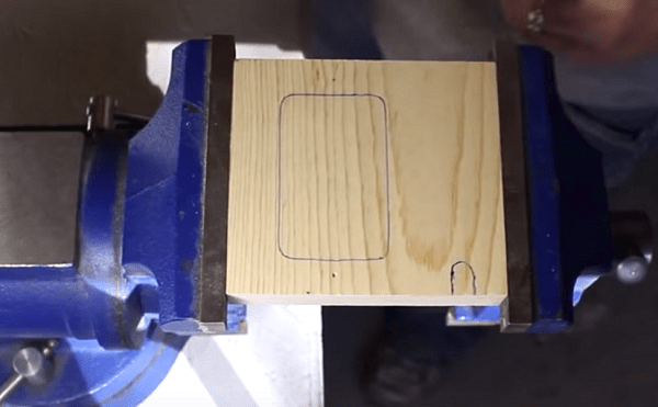
To connect the parts together, they can be screwed to a small piece of wood board.

If you measure the voltage on the secondary of the transformer, then in this case it will be equal to 31-32 V.

With such a home-made welder, metal 2 mm thick is easily welded with electrodes with a diameter of 2.5 mm.


It should be remembered that cooking with such a home-made apparatus should be done with breaks for rest, since its windings are very hot. On average, after each used electrode, the device should cool down for 20-30 minutes.
Thin metal with a unit made from a microwave will not be able to cook, as it will cut it. To adjust the current, a ballast resistor or choke can be connected to the welder. The role of a resistor can be performed by a piece of steel wire of a certain length (selected experimentally), which is connected to a low-voltage winding.
AC Welder
This is the most common type of apparatus for welding metals. It is easy to make at home, and it is unpretentious in operation. But the main disadvantage of the apparatus is large mass of step-down transformer, which is the basis of the aggregate.

For home use, it is enough that the device produces a voltage of 60 V and can provide a current of 120-160 A. Therefore, for primary, to which a 220 V household network is connected, a wire with a cross section of 3 mm 2 to 4 mm 2 is required. But perfect option- this is a conductor with a cross section of 7 mm 2. With such a cross section, voltage drops and possible additional loads will not be terrible for the device. From this it follows that for the secondary you need a conductor having a diameter of 3 mm. If we take an aluminum conductor, then the calculated cross section of the copper is multiplied by a factor of 1.6. For resale a copper bus with a cross section of at least 25 mm 2 is required
It is very important that the winding conductor is covered with rag insulation, since the traditional PVC sheath will melt when heated, which can cause an interturn short circuit.
If you did not find a wire with the required cross section, then it can be make your own from several thinner conductors. But at the same time, the thickness of the wire and, accordingly, the dimensions of the unit will increase significantly.
First thing, the basis of the transformer is made - the core. It is made of metal plates (transformer steel). These plates should have a thickness of 0.35-0.55 mm. The studs connecting the plates must be well insulated from them. Before assembling the core, its dimensions are calculated, that is, the dimensions of the “window” and the cross-sectional area of the core, the so-called “core”. To calculate the area, use the formula: S cm 2 \u003d a x b (see figure below).

But it is known from practice that if a core with an area of less than 30 cm 2 is made, then it will be difficult to obtain a high-quality seam with such an apparatus due to a lack of power reserve. Yes, and it will heat up very quickly. Therefore, the cross section of the core must be at least 50 cm 2 . Despite the fact that the mass of the unit will increase, it will become more reliable.
To assemble the core, it is better to use L-shaped plates and place them as shown in the following figure until the thickness of the part reaches the required value.

At the end of the assembly, the plates must be fastened (at the corners) with bolts, then cleaned with a file and insulated with fabric insulation.
Now we can start transformer winding.

One caveat should be taken into account: the ratio of turns on the core should be 40% to 60%. This means that on the side where the primary is located, there should be fewer turns of the secondary. Due to this, at the start of welding, the winding with more turns will be partially switched off due to the occurrence of eddy currents. This will increase the current strength, which will positively affect the quality of the seam.
When the winding of the transformer is completed, the network cable is connected to the common wire and to the 215 turn branch. Welding cables are connected to the secondary winding. After that, the contact welding machine is ready for operation.
DC device
To cook cast iron or stainless steel, a DC apparatus is required. It can be made from a conventional transformer unit, if its secondary winding connect rectifier. Below is a diagram of a welding machine with a diode bridge.

Scheme of a welding machine with a diode bridge
The rectifier is assembled on D161 diodes, capable of withstanding 200A. They must be installed on radiators. Also, to equalize the current ripple, you will need 2 capacitors (C1 and C2) for 50 V and 1500 uF. This circuit also has a current regulator, the role of which is performed by the inductor L1. Welding cables are connected to contacts X5 and X4 (direct or reverse polarity), depending on the thickness of the metal to be joined.
Computer power supply inverter
It is impossible to make a welding machine from a computer power supply. But it is quite possible to use its case and some parts, as well as the fan. So, if you make an inverter with your own hands, then it can easily be placed in the PSU case from the computer. All transistors (IRG4PC50U) and diodes (KD2997A) must be installed on radiators without the use of gaskets. For cooling parts, it is desirable use a powerful fan, such as Thermaltake A2016. Despite their small size(80 x 80 mm), the cooler is capable of developing 4800 rpm. The fan also has a built-in speed controller. The latter are regulated using a thermocouple, which must be mounted on a radiator with installed diodes.
Advice! It is recommended to drill several additional holes in the PSU case for better ventilation and heat dissipation. The overheating protection installed on the radiators of the transistors is set to operate at a temperature of 70-72 degrees.
Below is a circuit diagram of a welding inverter (in high resolution), according to which you can make a device that fits in the PSU case.
The following photos show what components a homemade inverter welding machine consists of, and how it looks after assembly.


electric motor welder
To make a simple welding machine from the stator of an electric motor, it is necessary to select the motor itself that meets certain requirements, namely, that its power is from 7 to 15 kW.
Advice! It is best to use a 2A series motor, as it will have a large magnetic circuit window.
You can get the right stator in places where scrap metal is accepted. As a rule, it will be cleaned of wires and after a couple of blows with a sledgehammer it will split. But if the body is made of aluminum, then in order to remove the magnetic circuit from it, stator needs to be annealed.
Preparation for work
Place the stator with the hole up and place bricks under the part. Next, stack the wood inside and set it on fire. After a couple of hours of roasting, the magnetic core will easily separate from the body. If there are wires in the housing, they can also be removed from the grooves after heat treatment. As a result, you will receive a magnetic circuit cleaned of unnecessary elements.

This blank should be well saturate with oil varnish and let it dry. To speed up the process, you can use heat gun. Impregnation with varnish is done so that after removing the screeds, the package does not spill.
When the blank is completely dry, using the grinder, remove the ties located on it. If the ties are not removed, they will act as short-circuited turns and take power from the transformer, as well as cause it to heat up.
After cleaning the magnetic circuit from unnecessary parts, you will need to make two end caps(see picture below).

The material for their manufacture can be either cardboard or pressboard. You also need to make two sleeves from these materials. One will be internal, and the second - external. Next, you need:
- install both end plates on the blank;
- then insert (dress) the cylinders;
- wrap all this structure with keeper or glass tape;
- impregnate the resulting part with varnish and dry.
Transformer manufacturing
After carrying out the above steps, it will be possible to make a welding transformer from the magnetic circuit. For these purposes, you will need a wire covered with fabric or glass-enamel insulation. To wind the primary winding, you need a wire with a diameter of 2-2.5 mm. The secondary winding will require about 60 meters of copper bus (8 x 4 mm).
So, the calculations are done as follows.
- 20 turns of wire with a diameter of at least 1.5 mm should be wound on the core, after which 12 V must be applied to it.
- Measure the current flowing in this winding. The value should be about 2 A. If the value is greater than the required, then the number of turns must be increased, if the value is less than 2A, then reduced.
- Count the number of turns obtained and divide it by 12. As a result, you will get a value that indicates how many turns per 1 V of voltage.
For primary winding a conductor with a diameter of 2.36 mm is suitable, which needs to be folded in half. In principle, you can take any wire with a diameter of 1.5-2.5 mm. But first you need to calculate the cross section of the conductors in the coil. First you need to wind the primary winding (at 220 V), and then the secondary. Its wire must be insulated along its entire length.
If you make a tap in the secondary winding in the area where 13 V is obtained and put a diode bridge, then this transformer can be used instead of the battery if you want to start the car. For welding, the voltage on the secondary winding should be in the range of 60-70 V, which will allow the use of electrodes with a diameter of 3 to 5 mm.
If you have laid both windings, and there is free space in this design, then you can add 4 turns of a copper bus bar (40 x 5 mm). In this case, you will receive a winding for spot welding, which will allow you to connect sheet metal up to 1.5 mm thick.
For case manufacturing metal is not recommended. It is better to make it from textolite or plastic. In places where the coil is attached to the body, rubber gaskets should be laid to reduce vibration and better insulation from conductive materials.

Homemade spot welding machine
The finished spot welding machine has a rather high price, which does not justify its internal “stuffing”. It is arranged very simply, and it will not be difficult to make it yourself.

To make a spot welding machine yourself, you need one transformer from a microwave oven with a power of 700-800 watts. It is necessary to remove the secondary winding from it in the manner described above, in the section where the manufacture of a microwave welding machine was considered.
The spot welding machine is made in the following way.
- Make 2-3 turns inside the manitoduct with a cable with a conductor diameter of at least 1 cm. This will be the secondary winding, which allows you to get a current of 1000 A.

- It is recommended to install copper lugs at the ends of the cable.

- If you connect 220 V to the primary winding, then on the secondary winding we will get a voltage of 2 V with a current strength of about 800 A. This will be enough to melt an ordinary nail in a few seconds.


- Followed by make a case for the device. Good for base wooden plank, from which several elements should be made, as shown in the following figure. The dimensions of all parts can be arbitrary and depend on the dimensions of the transformer.


- To give the case a more aesthetic appearance, sharp corners can be removed with manual router with an edge moulder mounted on it.


- On one part of the welding tongs, it is necessary cut a small wedge. Thanks to him, ticks will be able to rise higher.


- Cut holes on the back wall of the case for the switch and the mains cable.
- When all the details are ready and sanded, they can be painted with black paint or varnished.

- From an unnecessary microwave, you will need to disconnect the mains cable and limit switch. You will also need a metal door handle.


- If you do not have a switch and a copper rod lying around at home, as well as copper clips, then these parts must be purchased.

- From the copper wire, cut 2 small rods that will act as electrodes and fix them in the clamps.


- Screw the switch to the rear wall of the device.

- Screw the back wall and 2 posts to the base, as shown in the following photos.


- Attach the transformer to the base.

- Next, one mains wire is connected to the primary winding of the transformer. The second network wire is connected to the first terminal of the switch. Then you need to attach the wire to the second terminal of the switch and connect it to another output of the primary. But on this wire you should make a gap and install in it microwave interrupter. It will act as a welding start button. These wires must be long enough to accommodate a breaker at the end of the clamp.
- Fasten the cover of the device with the handle installed on the racks and the rear wall.

- Fasten the side walls of the case.

- Now you can install the welding tongs. First, drill a hole at their ends into which the screws will be screwed.

- Next, attach the switch to the end.

- Insert the pliers into the housing, after placing a square bar between them for alignment. Drill holes in the pliers through the side walls and insert long nails into them to serve as axes.


- Attach copper electrodes to the ends of the clamps and align them so that the ends of the rods are opposite each other.


- To make the top electrode rise automatically, screw in 2 screws and fix the elastic band on them, as shown in the following photos.


- Turn on the unit, connect the electrodes and press the start button. You should see an electrical discharge between the copper bars.

- To check the operation of the unit, you can take metal washers and weld them.


In this case, the result was positive. Therefore, the creation of a spot welding machine can be considered completed.
It is quite possible to make a welding inverter with your own hands, even without in-depth knowledge in electronics and electrical engineering, the main thing is to strictly adhere to the scheme and try to understand well how such a device works. If you make an inverter, specifications and the efficiency of which will differ little from similar parameters of serial models, you can save a decent amount.
You should not think that a home-made device will not give you the opportunity to effectively carry out welding work. Such a device, even assembled according to a simple scheme, will allow you to weld with electrodes with a diameter of 3-5 mm and an arc length of 10 mm.
Characteristics of a homemade inverter and materials for its assembly
By assembling a welding inverter with your own hands according to a fairly simple electrical circuit, you will get efficient device with the following technical characteristics:
- the value of the consumed voltage - 220 V;
- the strength of the current supplied to the input of the device - 32 A;
- the current generated at the output of the device is 250 A.
During operation, the diodes of such a bridge get very hot, so they must be mounted on radiators, which can be used as cooling elements from old computers. To mount the diode bridge, it is necessary to use two radiators: the upper part of the bridge is attached to one radiator through a mica gasket, the lower part through a layer of thermal paste to the second one.
The conclusions of the diodes from which the bridge is formed must be directed in the same direction as the conclusions of the transistors, with the help of which the direct current will be converted into high-frequency alternating current. The wires connecting these terminals should be no longer than 15 cm. Between the power supply and the inverter unit, which is based on transistors, there is a sheet of metal attached to the body of the device by welding.

Power block
The basis of the power unit of the welding inverter is a transformer, due to which the value of the high-frequency voltage decreases, and its strength increases. In order to make a transformer for such a block, it is necessary to select two cores Ш20х208 2000 nm. Newsprint can be used to provide a gap between them.
The windings of such a transformer are not made of wire, but of a copper strip 0.25 mm thick and 40 mm wide.
Each layer is wrapped with cash register tape to provide thermal insulation, which demonstrates good wear resistance. The secondary winding of the transformer is formed from three layers of copper strips, which are isolated from each other using a fluoroplastic tape. The characteristics of the transformer windings must comply with the following parameters: 12 turns x 4 turns, 10 kv. mm x 30 sq. mm.
Many people try to make step-down transformer windings from thick copper wire, but this is not the right solution. Such a transformer operates on high-frequency currents, which are forced out to the surface of the conductor without heating its interior. That is why for the formation of windings the best option is a conductor with a large surface area, that is, a wide copper strip.

Plain paper can also be used as a thermal insulation material, but it is less wear-resistant than cash register tape. From elevated temperature, such a tape will darken, but its wear resistance will not suffer from this.
The transformer of the power unit will become very hot during its operation, therefore, for its forced cooling, it is necessary to use a cooler, which can be used as a device previously used in the computer system unit.
inverter unit
Even a simple welding inverter must perform its main function - to convert the direct current generated by the rectifier of such an apparatus into high-frequency alternating current. To solve this problem, power transistors are used that open and close at a high frequency.
circuit diagram inverter unit (click to enlarge)
The inverter unit of the apparatus, which is responsible for converting direct current to high-frequency alternating current, is best assembled on the basis of not one powerful transistor, but several less powerful ones. Such a constructive solution will allow to stabilize the current frequency, as well as to minimize noise effects during welding.
The electronic also contains capacitors connected in series. They are necessary to solve two main tasks:
- minimization of resonant emissions of the transformer;
- reducing losses in the transistor block that occur when it is turned off and due to the fact that the transistors open much faster than they close (at this moment, current losses may occur, accompanied by heating of the transistor block keys).

Cooling system
The power elements of the home-made welding inverter circuit become very hot during operation, which can lead to their failure. To prevent this from happening, in addition to the radiators on which the most heated blocks are mounted, it is necessary to use fans responsible for cooling.
If you have a powerful fan available, you can get by with one by directing the air flow from it to a step-down power transformer. If you are using low-power fans from older computers, you will need about six of them. At the same time, three such fans should be installed next to the power transformer, directing the air flow from them to it.

To prevent overheating of a homemade welding inverter, you should also use a temperature sensor by installing it on the hottest radiator. Such a sensor, in the event that the radiator reaches a critical temperature, will turn off the flow electric current on him.
In order for the inverter ventilation system to work effectively, properly executed air intakes must be present in its case. The grilles of such intakes, through which air flows will flow into the device, should not be blocked by anything.
Do-it-yourself inverter assembly
For a home-made inverter device, you need to choose a reliable case or make it yourself, using sheet metal with a thickness of at least 4 mm. As a base on which the welding inverter transformer will be mounted, you can use a sheet of getinax with a thickness of at least 0.5 cm. The transformer itself is mounted on such a base using brackets that you can make yourself from copper wire with a diameter of 3 mm.

To create electronic circuit boards of the device, you can use foil textolite with a thickness of 0.5–1 mm. When installing magnetic circuits that will heat up during operation, it is necessary to provide for gaps between them necessary for free air circulation.
For automatic control, you will need to purchase and install a PWM controller in it, which will be responsible for stabilizing the welding current and voltage. To make it convenient for you to work with your home-made device, it is necessary to mount controls in the front of its body. Such bodies include a toggle switch for turning on the device, a variable resistor knob with which the welding current is regulated, as well as cable clamps and signal LEDs.

Diagnostics of a homemade inverter and its preparation for work
Doing is half the battle. An equally important task is its preparation for work, during which the correct functioning of all elements is checked, as well as their configuration.
The first thing to do when testing a homemade welding inverter is to apply 15 V to the PWM controller and one of the cooling fans. This will allow you to simultaneously check the performance of the controller and avoid its overheating during such a test.

After the capacitors of the device are charged, a relay is connected to the electrical supply, which is responsible for closing the resistor. If voltage is applied directly to the resistor, bypassing the relay, an explosion may occur. After the relay trips, which should happen within 2-10 seconds after the voltage is applied to the PWM controller, you need to check if the resistor has closed.
When the relays of the electronic circuit work, the PWM board should form rectangular pulses to the optocouplers. This can be checked using an oscilloscope. The correct assembly of the diode bridge of the device must also be checked; for this, a voltage of 15 V is applied to it (the current strength should not exceed 100 mA).
The transformer phases may have been connected incorrectly during the assembly of the device, which may lead to incorrect operation of the inverter and strong noise. To prevent this from happening, the correct connection of the phases must be checked; for this, a two-beam oscilloscope is used. One beam of the device is connected to the primary winding, the second - to the secondary. The phases of the pulses, if the windings are connected correctly, should be the same.

The correctness of the manufacture and connection of the transformer is checked using an oscilloscope and connecting electrical devices with various resistances to the diode bridge. Focusing on the noise of the transformer and the readings of the oscilloscope, they conclude that it is necessary to refine in electronic circuit homemade inverter device.
To check how much you can continuously work on a homemade inverter, you need to start testing it from 10 seconds. If the radiators of the device do not heat up during operation of this duration, you can increase the period to 20 seconds. If such a time period did not negatively affect the state of the inverter, you can increase the duration of the welding machine up to 1 minute.
Maintenance of a homemade welding inverter
In order for the inverter device to serve for a long time, it must be properly maintained.
In the event that your inverter has stopped working, you need to open its cover and blow out the insides with a vacuum cleaner. Those places where dust remains can be thoroughly cleaned with a brush and a dry cloth.
The first thing to do when diagnosing a welding inverter is to check the voltage supply to its input. If the voltage is not supplied, you should diagnose the performance of the power supply. The problem in this situation may also be that the fuses of the welding machine have blown. Another weak link of the inverter is the temperature sensor, which, in the event of a breakdown, must not be repaired, but replaced.

When performing diagnostics, it is necessary to pay attention to the quality of the connections of the electronic components of the device. Poorly made connections can be determined visually or using a tester. If such connections are identified, they must be corrected so as not to encounter further overheating and failure of the welding inverter.
Only if you pay due attention to the maintenance of the inverter device, you can count on the fact that it will serve you for a long time and will enable you to perform welding work as efficiently and efficiently as possible.
5 , average rating: 3,20
out of 5)
Figure 1. Scheme of a bridge rectifier for a welding machine.
Welding machines are of direct and alternating current.
S.A. direct current are used for welding at low currents of thin sheet metal (roofing steel, automotive, etc.). DC welding arc is more stable, direct and reverse polarity welding is possible. At direct current, it is possible to cook with electrode wire without coating and electrodes intended for welding, both at direct current and at alternating current. To make the arc burning stable at low currents, it is desirable to have an increased open-circuit voltage Uxx of the welding winding (up to 70 - 75 V). To rectify alternating current, the simplest "bridge" rectifiers on powerful diodes with cooling radiators are used (Fig. 1).
To smooth out voltage ripples, one of the conclusions of S.A. A is connected to the electrode holder through the L1 choke, which is a coil of 10 - 15 turns of a copper bus with a cross section of S = 35 mm 2, wound on any core, for example, from. For rectification and smooth regulation of the welding current, more complex circuits are used using powerful controlled thyristors. One of the possible circuits based on thyristors of the T161 (T160) type is given in the article by A. Chernov “And it will charge and weld” (Model designer, 1994, No. 9). The advantage of DC regulators is their versatility. The range of voltage change by them is 0.1-0.9 Uxx, which allows them to be used not only for smooth adjustment welding current, but also for charging batteries, powering electric heating elements and other purposes.

Figure 2. Scheme of the falling external characteristic of the welding machine.
Rice. 1. Bridge rectifier for welding machine. S.A. connection shown. for welding thin sheet metal on the "reverse" polarity - "+" on the electrode, "-" on the workpiece to be welded U2: - output alternating voltage of the welding machine
AC welding machines are used for welding with electrodes whose diameter is more than 1.6 - 2 mm, and the thickness of the welded products is more than 1.5 mm. In this case, the welding current is significant (tens of amperes) and the arc burns quite steadily. Electrodes designed for welding only on alternating current are used. For normal operation of the welding machine, it is necessary:
- Provide output voltage for reliable arc ignition. For amateur S.A. Uxx \u003d 60 - 65v. A higher no-load output voltage is not recommended, which is mainly due to the safety of operation (Uxx industrial welding machines - up to 70 - 75 V).
- Provide the welding voltage Usv necessary for stable arc burning. Depending on the diameter of the electrode - Usv \u003d 18 - 24v.
- Ensure the rated welding current Iw = (30 - 40) de, where Iw is the value of the welding current, A; 30 - 40 - coefficient depending on the type and diameter of the electrode; de - electrode diameter, mm.
- Limit the short-circuit current Ikz, the value of which should not exceed the rated welding current by more than 30 - 35%.
Stable arc burning is possible if the welding machine has a falling external characteristic, which determines the relationship between the current strength and voltage in the welding circuit (Fig. 2).
S.A. shows that for a rough (stepped) overlapping of the range of welding currents, it is necessary to switch both the primary windings and the secondary ones (which is structurally more difficult due to the large current flowing in it). In addition, mechanical devices for moving the windings are used to smoothly change the welding current within the selected range. When the welding winding is removed relative to the mains, the leakage magnetic fluxes increase, which leads to a decrease in the welding current.

Figure 3. Scheme of a rod-type magnetic circuit.
When designing an amateur S.A., one should not strive to completely cover the range of welding currents. It is advisable at the first stage to assemble a welding machine for working with electrodes with a diameter of 2–4 mm, and at the second stage, if it is necessary to work at low welding currents, supplement it with a separate rectifier device with smooth regulation of the welding current. Amateur welding machines must meet a number of requirements, the main of which are the following: relative compactness and low weight; sufficient duration of operation (at least 5 - 7 electrodes de = 3 - 4 mm) from a 220v network.
The weight and dimensions of the device can be reduced by reducing its power, and increasing the duration of operation by using steel with high magnetic permeability and heat-resistant insulation of the winding wires. These requirements are easy to meet, knowing the basics of designing welding machines and adhering to the proposed technology for their manufacture.
Rice. 2. Falling external characteristic of the welding machine: 1 - a family of characteristics for different welding ranges; Iw2, Iwv, Iw4 - ranges of welding currents for electrodes with a diameter of 2, 3 and 4 mm, respectively; Uxx - no-load voltage of SA. Ikz - short circuit current; Ucv - welding voltage range (18 - 24 V).
Rice. 3. Rod-type magnetic circuit: a - L-shaped plates; b - U-shaped plates; c - plates from strips of transformer steel; S \u003daxb- cross-sectional area of \u200b\u200bthe core (core), cm 2 s, d- window dimensions, cm.
So, the choice of the type of core. For the manufacture of welding machines, mainly rod-type magnetic cores are used, since they are more technologically advanced in design. The core is recruited from electrical steel plates of any configuration with a thickness of 0.35-0.55 mm, tightened with studs isolated from the core (Fig. 3). When selecting the core, it is necessary to take into account the dimensions of the "window" to fit the windings of the welding machine, and the cross-sectional area of the core (core) S =axb, cm 2. As practice shows, the minimum values \u200b\u200bS = 25 - 35 cm should not be chosen, since the welding machine will not have the required power reserve and it will be difficult to obtain high-quality welding. Yes, and overheating of the welding machine after a short operation is also inevitable.

Figure 4. Scheme of a toroidal type magnetic circuit.
The cross section of the core should be S = 45 - 55 cm 2. The welding machine will be somewhat heavier, but will not let you down! Amateur welding machines on toroidal-type cores are becoming more widespread, which have higher electrical characteristics, about 4-5 times higher than those of the rod, and electrical losses are small. The labor costs for their manufacture are more significant and are associated primarily with the placement of the windings on the torus and the complexity of the winding itself.
However, with the right approach, they give good results. The cores are made from tape transformer iron rolled into a roll in the shape of a torus. An example is the core from the autotransformer "Latr" by 9 A. To increase the inner diameter of the torus ("window"), a part of the steel tape is unwound from the inside and wound on the outer side of the core. But, as practice shows, one "Latra" is not enough for the manufacture of high-quality S.A. (small section S). Even after working with 1 - 2 electrodes with a diameter of 3 mm, it overheats. It is possible to use two similar cores according to the scheme described in the article by B. Sokolov "Welding Kid" (Sam, 1993, No. 1), or to manufacture one core by rewinding two (Fig. 4).
Rice. 4. Toroidal type magnetic circuit: 1.2 - autotransformer core before and after rewinding; 3 design S.A. based on two toroidal cores; W1 1 W1 2 - network windings connected in parallel; W 2 - welding winding; S =axb- cross-sectional area of the core, cm 2, s, d- inner and outer diameters of the torus, cm; 4 - electrical circuit S.A. based on two joined toroidal cores.
Amateur S.A., made on the basis of stators of asynchronous three-phase electric motors of high power (more than 10 kW), deserve special attention. The choice of the core is determined by the cross-sectional area of the stator S. The stamped stator plates do not fully correspond to the parameters of electrical transformer steel, therefore it is not advisable to reduce the cross section S to less than 40 - 45 cm.

Figure 5. Scheme of fastening the leads of the SA windings.
The stator is freed from the body, the stator windings are removed from the internal grooves, the groove jumpers are cut with a chisel, the inner surface is protected with a file or an abrasive wheel, the sharp edges of the core are rounded and wrapped tightly, with an overlap of cotton insulating tape. The core is ready for winding windings.
Winding selection. For primary (network) windings, it is better to use a special copper winding wire in cotton. (fiberglass) insulation. Satisfactory heat resistance is also possessed by wires in rubber or rubber-fabric insulation. Unsuitable for operation at elevated temperatures (and this is already being incorporated into the design of an amateur S.A.) wires in polyvinyl chloride (PVC) insulation due to its possible melting, leakage from the windings and their short circuit. Therefore, PVC insulation from the wires must either be removed and wrapped around the wires along the entire length of the coil. with insulating tape, or do not remove, but wrap the wire over the insulation. Another proven method of winding is also possible. But more on that below.
When selecting the section of the winding wires, taking into account the specifics of the work of S.A. (periodic) allow a current density of 5 A / mm 2. At a welding current of 130 - 160 A (electrode de \u003d 4 mm), the power of the secondary winding will be P 2 \u003d Iw x 160x24 \u003d 3.5 - 4 kW, the power of the primary winding, taking into account losses, will be about 5-5.5 kW, and therefore, the maximum current of the primary winding can reach 25 A. Therefore, the cross section of the wire of the primary winding S 1 must be at least 5 - 6 mm. In practice, it is desirable to use a wire with a cross section of 6 - 7 mm 2. Either it is a rectangular bus, or a copper winding wire with a diameter (without insulation) of 2.6 - 3 mm. (Calculation according to the well-known formula S \u003d piR 2, where S is the area of \u200b\u200bthe circle, mm 2 pi \u003d 3.1428; R is the radius of the circle, mm.) If the cross section of one wire is insufficient, winding in two is possible. When using aluminum wire, its cross section must be increased by 1.6 - 1.7 times. Is it possible to reduce the cross section of the wire of the network winding? Yes, you can. But at the same time, S.A. will lose the required power reserve, will heat up faster, and the recommended core cross section S = 45 - 55 cm in this case will be unreasonably large. The number of turns of the primary winding W 1 is determined from the following relationship: W 1 \u003d [(30 - 50): S] x U 1 where 30-50 is a constant coefficient; S- core section, cm 2, W 1 = 240 turns with taps from 165, 190 and 215 turns, i.e. every 25 turns.

Figure 6. Scheme of winding methods for SA windings on a rod-type core.
More taps of the network winding, as practice shows, is not practical. And that's why. By reducing the number of turns of the primary winding, both the power SA and Uxx increase, which leads to an increase in the arcing voltage and a deterioration in the quality of welding. Therefore, only by changing the number of turns of the primary winding, it is impossible to achieve overlapping of the range of welding currents without deteriorating the quality of welding. To do this, it is necessary to provide for switching turns of the secondary (welding) winding W 2.
The secondary winding W 2 must contain 65 - 70 turns of a copper insulated bus with a cross section of at least 25 mm (better with a cross section of 35 mm). A flexible stranded wire (for example, welding) and a three-phase power stranded cable are quite suitable. The main thing is that the cross section of the power winding should not be less than required, and the insulation should be heat-resistant and reliable. If the wire section is insufficient, winding in two or even three wires is possible. When using aluminum wire, its cross section must be increased by 1.6 - 1.7 times.
Rice. 5. Fastening the leads of the SA windings: 1 - SA case; 2 - washers; 3 - terminal bolt; 4 - nut; 5 - copper tip with wire.
The difficulty of acquiring switches for high currents, and practice shows that it is easiest to lead the welding winding leads through copper lugs under terminal bolts with a diameter of 8 - 10 mm (Fig. 5). Copper lugs are made from copper tubes of suitable diameter 25 - 30 mm long and are attached to the wires by crimping and preferably by soldering. Let us dwell in particular on the order of winding the windings. General rules:
- Winding must be carried out on an insulated core and always in the same direction (for example, clockwise).
- Each layer of the winding is insulated with a layer of cotton. insulation (fiberglass, electric cardboard, tracing paper), preferably impregnated with bakelite varnish.
- The conclusions of the windings are tinned, marked, and fixed. braid, on the conclusions of the network winding additionally put on h.b. cambric.
- In case of doubt about the quality of the insulation, winding can be carried out using a cotton cord, as it were, in two wires (the author used a cotton thread for fishing). After winding one layer, the winding with cotton the thread is fixed with glue, varnish, etc. and after drying, the next row is wound.

Figure 7. Scheme of winding methods for SA windings on a toroidal type core.
Consider the arrangement of windings on a rod-type magnetic circuit. The network winding can be positioned in two main ways. The first method allows you to get a more "hard" welding mode. The network winding in this case consists of two identical windings W 1 W 2 located on different sides of the core, connected in series and having the same wire cross section. To adjust the output current, taps are made on each of the windings, which are closed in pairs (Fig. 6a, c).
The second method involves winding the primary (network) winding on one of the sides of the core (Fig. 6 c, d). In this case, the SA has a steeply falling characteristic, it welds “softly”, the arc length has less effect on the magnitude of the welding current, and, consequently, on the quality of welding. After winding the primary winding of the CA, it is necessary to check for the presence of short-circuited turns and the correctness of the selected number of turns. The welding transformer is connected to the network through a fuse (4 - 6A) and preferably an AC ammeter. If the fuse burns out or gets very hot, then this is a clear sign of a shorted coil. Therefore, the primary winding will have to be rewound, paying special attention to the quality of the insulation.
Rice. 6. Ways of winding SA windings on a rod-type core: a - network winding on both sides of the core; b - the secondary (welding) winding corresponding to it, connected in anti-parallel; c - network winding on one side of the core; g - the secondary winding corresponding to it, connected in series.
If the welding machine is very buzzing, and the current consumption exceeds 2 - 3 A, then this means that the number of primary windings is underestimated and it is necessary to rewind a certain number of turns. A serviceable SA consumes no more than 1 - 1.5 A of idle current, does not heat up and does not buzz very much. The secondary winding CA is always wound on two sides of the core. For the first winding method, the secondary winding also consists of two identical halves, connected in anti-parallel to increase the stability of the arc (Fig. 6), and the wire cross section can be taken somewhat less - 15 - 20 mm 2.

Figure 8. Measuring instrument connection diagram.
For the second winding method, the main welding winding W 2 1 is wound on the side of the core free from windings and makes up 60 - 65% of the total number of turns of the secondary winding. It serves mainly to ignite the arc, and during welding, due to a sharp increase in the magnetic leakage flux, the voltage on it drops by 80 - 90%. Additional welding winding W 2 2 is wound over the primary. Being power, it maintains the welding voltage within the required limits, and, consequently, the welding current. The voltage on it drops in the welding mode by 20 - 25% relative to the open circuit voltage. After manufacturing SA, it is necessary to set it up and check the quality of welding with electrodes of various diameters. The setup process is as follows. To measure the welding current and voltage, it is necessary to purchase two electrical measuring instruments - an AC ammeter for 180-200 A and an AC voltmeter for 70-80V.
Rice. 7. Ways of winding SA windings on a toroidal type core: 1.2 - uniform and sectional winding of the windings, respectively: a - network b - power.
The scheme of their connection is shown in fig. 8. When welding with different electrodes, the values of the welding current - Iw and the welding voltage Uw are taken, which must be within the required limits. If the welding current is small, which happens most often (the electrode sticks, the arc is unstable), then in this case, either by switching the primary and secondary windings, the required values \u200b\u200bare set, or the number of turns of the secondary winding is redistributed (without increasing them) in the direction of increasing the number of turns wound over network winding. After welding, you can make a break or saw the edges of the welded products, and the quality of welding will immediately become clear: the depth of penetration and the thickness of the deposited metal layer. Based on the results of measurements, it is useful to make a table.
![]()
Figure 9. Scheme of welding voltage and current meters and the design of the current transformer.
Based on the data in the table, the optimal welding modes are selected for electrodes of various diameters, remembering that when welding with electrodes, for example, with a diameter of 3 mm, electrodes with a diameter of 2 mm can be cut, because. cutting current is 30-25% more than welding current. The difficulty of purchasing the measuring instruments recommended above made the author resort to making a measuring circuit (Fig. 9) based on the most common 1-10 mA direct current milliammeter. It consists of voltage and current meters assembled in a bridge circuit.
Rice. 9. Schematic diagram of welding voltage and current meters and the design of the current transformer.
The voltage meter is connected to the output (welding) winding S.A. The setting is carried out using any tester that controls the welding output voltage. With the help of variable resistance R.3, the pointer of the device is set to the final division of the scale at the maximum value of Uxx. The scale of the voltage meter is quite linear. For greater accuracy, you can remove two or three control points and calibrate measuring device for voltage measurement.
It is more difficult to set up a current meter because it is connected to a self-made current transformer. The latter is a toroidal type core with two windings. The dimensions of the core (outer diameter 35-40 mm) are of no fundamental importance, the main thing is that the windings fit. Core material - transformer steel, permalloy or ferrite. The secondary winding consists of 600 - 700 turns of insulated copper wire PEL, PEV, preferably PELSHO with a diameter of 0.2 - 0.25 mm and is connected to a current meter. The primary winding is a power wire passing inside the ring and connected to the terminal bolt (Fig. 9). Setting up the current meter is as follows. To the power (welding) winding S.A. connect a calibrated resistance from a thick nichrome wire for 1 - 2 seconds (it gets very hot) and measure the voltage at the output of S.A. By determine the current flowing in the welding winding. For example, when connecting Rn = 0.2 ohm Uout = 30v.

Mark a point on the instrument scale. Three to four measurements with different R H are enough to calibrate the current meter. After calibration, the instruments are mounted on the C.A case, using generally accepted recommendations. When welding in various conditions(strong or low-current network, long or short supply cable, its cross section, etc.) adjust S.A. by switching the windings. to the optimal welding mode, and then the switch can be set to the neutral position. A few words about contact-spot welding. To the design of S.A. This type has a number of specific requirements:
- The power given off at the time of welding should be maximum, but not more than 5-5.5 kW. In this case, the current consumed from the network will not exceed 25 A.
- The welding mode must be "hard", and therefore, the winding of the windings S.A. should be carried out according to the first option.
- The currents flowing in the welding winding reach values of 1500-2000 A and above. Therefore, the welding voltage should be no more than 2-2.5V, and the open-circuit voltage should be 6-10V.
- The cross section of the wires of the primary winding is at least 6-7 mm, and the cross section of the secondary winding is at least 200 mm. Such a cross-section of wires is achieved by winding 4-6 windings and their subsequent parallel connection.
- It is not advisable to make additional taps from the primary and secondary windings.
- The number of turns of the primary winding can be taken as the minimum calculated due to the short duration of the work of S.A.
- It is not recommended to take a core (core) section less than 45-50 cm.
- Welding tips and submarine cables to them must be copper and pass the appropriate currents (tip diameter 12-14 mm).
![]()
Special class amateur S.A. represent devices made on the basis of industrial lighting and other transformers (2-3 phase) for an output voltage of 36V and a power of at least 2.5-3 kW. But before taking on the alteration, it is necessary to measure the cross section of the core, which must be at least 25 cm, and the diameters of the primary and secondary windings. It will immediately become clear to you what you can expect from the alteration of this transformer.
And finally, a few technological tips.
The connection of the welding machine to the network should be made with a wire with a cross section of 6-7 mm through an automatic machine for a current of 25-50 A, for example, AP-50. The electrode diameter, depending on the thickness of the metal to be welded, can be selected based on the following relationship: da= (1-1.5)L, where L is the thickness of the metal to be welded, mm.
The length of the arc is selected depending on the diameter of the electrode and is on average 0.5-1.1 d3. It is recommended to weld with a short arc of 2-3 mm, the voltage of which is 18-24 V. An increase in the length of the arc leads to a violation of the stability of its combustion, an increase in waste losses and spatter, and a decrease in the depth of penetration of the base metal. The longer the arc, the higher the welding voltage. The welding speed is chosen by the welder depending on the grade and thickness of the metal.
![]()
When welding in direct polarity, the plus (anode) is connected to the workpiece and the minus (cathode) to the electrode. If it is necessary that less heat is generated on the parts, for example, when welding thin-sheet structures, reverse polarity welding is used (Fig. 1). In this case, the minus (cathode) is attached to the workpiece to be welded, and the plus (anode) is attached to the electrode. This not only ensures less heating of the welded part, but also accelerates the process of melting the electrode metal due to more high temperature anode zone and greater heat input.
Welding wires are connected to the SA through copper lugs under the terminal bolts on the outside of the body of the welding machine. Poor contact connections reduce the power characteristics of the SA, worsen the quality of welding and can cause them to overheat and even ignite the wires. With a small length of welding wires (4-6 m), their cross section must be at least 25 mm. When performing welding work, it is necessary to follow the rules of fire and electrical safety when working with electrical appliances.
Welding work should be carried out in a special mask with protective glass grade C5 (for currents up to 150-160 A) and gloves. All switching of the SA should be carried out only after disconnecting the welding machine from the mains.
It makes sense to independently manufacture a welding machine when it is necessary to perform relatively small amounts of welding work at home. Knowing the basic principles of the apparatus, you can assemble it from easily accessible parts and materials.
First of all, it is worth determining what power the welding current will require in work. Obviously, for processing thin sheets of metal up to 2 mm, a much lower current intensity is needed than for massive reinforcement. Depending on these characteristics of the material, the diameter of the electrode is selected. For welded parts up to 2 mm thick, an electrode 1.5 - 3 mm in diameter is suitable. Accordingly, for parts 3-5 mm - electrode 3-4 mm, parts up to 10 mm - electrode 4-5 mm, parts up to 24 mm - electrode 5-6 mm and parts up to 60 mm - electrode 6-8 mm. Having determined the diameter of the electrode, we select the required value of the welding current. For electrodes with a diameter of up to 1.5 mm, a welding current of 4o A is suitable, 2 mm - 70 A, 3 mm - up to 140 A, 4 mm - up to 200 A.


A welding machine made independently using carefully selected components can fully replace an expensive finished machine and reliably serve the owner for many years.


