How to assemble a simple electric motor at home. Do-it-yourself electric motor: instructions for assembling a homemade mechanism. Possible modifications and the simplest models How to make an electric motor at home
It is always interesting to observe changing phenomena, especially if you yourself participate in the creation of these phenomena. Now we will assemble the simplest (but really working) electric motor, consisting of a power source, a magnet and a small coil of wire, which we ourselves will make.
There is a secret that will make this set of items become an electric motor; a secret that is both clever and amazingly simple. Here's what we need:
1.5V battery or accumulator.
Holder with contacts for the battery.
Magnet.
1 meter of wire with enamel insulation (diameter 0.8-1 mm).
0.3 meters of bare wire (diameter 0.8-1 mm).


We'll start by winding the coil, the part of the motor that will spin. To make the coil sufficiently even and round, we wind it on a suitable cylindrical frame, for example, on an AA battery.
Leaving 5 cm of wire free at each end, we wind 15-20 turns on a cylindrical frame.
Don't try to wind the spool too tightly and evenly, a small degree of freedom will help the spool retain its shape better.
Now carefully remove the coil from the frame, trying to maintain the resulting shape.
Then wrap the free ends of the wire several times around the turns to keep the shape, making sure that the new binding turns are exactly opposite each other.
The coil should look like this: 

Now it's time for the secret, the feature that will make the motor work. It's a secret because it's a subtle and non-obvious trick, and it's very hard to detect when the motor is running. Even people who know a lot about the operation of engines may be surprised by the ability of the motor to work until they discover this subtlety.
Holding the spool upright, place one of the free ends of the spool on the edge of a table. With a sharp knife, remove the top half of the insulation, leaving the bottom half in the enamel insulation.
Do the same with the other end of the coil, making sure that the bare ends of the wire are pointing up at the two free ends of the coil.
What is the meaning of this approach? The coil will lie on two holders made of bare wire. These holders will be attached to different ends of the battery, so that electricity could pass from one holder through the coil to another holder. But this will only happen when the bare halves of the wire are lowered down, touching the holders.
Now you need to make support for the coil. They are simply coils of wire that support the coil and allow it to spin. They are made of bare wire, since in addition to supporting the coil, they must deliver an electric current to it.
Just wrap each piece of bare wire around a small nail and you have the right part for our engine.
The base of our first electric motor will be the battery holder. This will be a suitable base, because at installed battery it will be heavy enough to keep the motor from shaking.
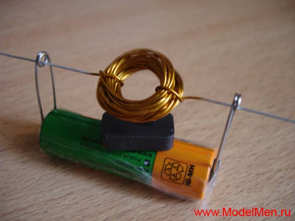
Assemble the five pieces together as shown in the picture (without the magnet at first). Put a magnet on top of the battery and gently push the coil... 

If done correctly, THE COIL WILL START SPINING FAST! We hope that you, as in our experiment, will work the first time.
If, nevertheless, the motor does not work, carefully check all electrical connections. Does the coil rotate freely? Is the magnet close enough (if not, install additional magnets or cut wire holders)?
When the motor starts, the only thing you need to pay attention to is that the battery does not overheat, since the current is quite large. Just remove the coil and the circuit will be broken.
Let's find out exactly how our the simplest electric motor. When an electric current flows through the wire of any coil, the coil becomes an electromagnet. The electromagnet acts like a normal magnet. It has a north and south pole and can attract and repel other magnets.
Our coil becomes an electromagnet when the uninsulated half of the protruding coil wire touches the uninsulated holder. At this moment, a current begins to flow through the coil, a north pole appears at the coil, which is attracted to the south pole permanent magnet, and the south pole, which is repelled by the south pole of the permanent magnet.
We stripped the top of the wire with the coil upright, so the poles of the electromagnet would point right and left. And this means that the poles will move to be in the same plane as the poles of the lying magnet, pointing up and down. Therefore, the coil will turn towards the magnet. But in doing so, the insulated part of the wire of the coil will touch the holder, the current will be interrupted, and the coil will no longer be an electromagnet. It will rotate further by inertia, again touch the non-insulated part of the holder, and the process will repeat again and again until the current runs out in the batteries.
How can you make an electric motor spin faster?
One way is to add another magnet on top.
Bring the magnet up while the coil is spinning, and one of two things will happen: either the motor will stop, or the motor will spin faster. The choice of one of the two options will depend on which pole of the new magnet will be directed towards the coil. Just remember to hold the bottom magnet, otherwise the magnets will jump to each other and destroy the fragile structure!
Another way is to put small glass beads on the axis of the coil, which will reduce the friction of the coil on the holders, as well as better balance the electric motor.
There are many more ways to improve this simple design, but we have achieved the main goal - you have assembled and fully understood how the simplest electric motor works.
Consider some aspects of design. We will not promise the manufacture of a perpetual motion machine, according to the type of creation attributed to Tesla, but the story is expected to be interesting. We will not disturb readers with paper clips and batteries, we propose to talk about how to adapt a ready-made motor for your own purposes. It is known that there are a lot of designs, all are used, but modern literature leaves the basic foundations behind the stern. The authors studied the textbook of the last century, learning how to make an electric motor with their own hands. Now we offer to plunge into the knowledge that makes up the basis of a specialist.
Why are collector motors often used in everyday life?
If we take the phase at 220V, the principle of operation of the electric motor on the collector makes it possible to make devices 2-3 times less massive than when using an asynchronous design. This is important in the manufacture of appliances: hand blenders, mixers, meat grinders. Among other things, it is difficult to accelerate an asynchronous motor above 3000 rpm; there is no specified limitation for collector motors. What makes the devices the only ones suitable for the implementation of designs of centrifugal juicers, not to mention vacuum cleaners, where the speed is often not lower.
There is no question of how to make an electric motor speed controller. The problem was solved a long time ago by cutting off part of the supply voltage sinusoid cycle. This is possible, because the collector motor does not care whether it is powered by a variable or direct current. In the first case, the characteristics fall, but the phenomenon is tolerated because of the obvious benefits. The electric motor of the collector type works and in washing machine, and in the dishwasher. Although the speeds are very different.
Easy to do and reverse. To do this, the polarity of the voltage on one winding is changed (if both are affected, the direction of rotation will remain the same). Another task is how to make an engine with a similar amount constituent parts. It is unlikely that it will be possible to make a collector on your own, but it is quite possible to rewind and pick up a stator. Note that the rotation speed depends on the number of rotor sections (similar to the amplitude of the supply voltage). And on the stator there are only a couple of poles.
Finally, when using this design, it is possible to create a universal device. The motor runs easily on both AC and DC. It’s just that a tap is made on the winding, when turned on from the rectified voltage, the turns are fully used, and with a sinusoidal only a part. This allows you to keep the nominal parameters. Making a primitive collector-type electric motor does not look like an easy task, but it will be possible to fully adapt the parameters to your own needs.
Features of the collector motors
In a commutator motor, there are not too many poles on the stator. To be more precise, there are only two - northern and southern. The magnetic field, as opposed to asynchronous motors, does not rotate here. Instead, the position of the poles on the rotor changes. This state of affairs is ensured by the fact that the brushes gradually move along the sections of the copper drum. The special winding of the coils ensures proper distribution. The poles seem to slide around the circle of the rotor, pushing it in the right direction.
To ensure the reverse mode, it is enough to change the polarity of the power supply of any winding. The rotor in this case is called the armature, and the stator is called the exciter. It is permissible to include these circuits in parallel to each other or in series. And then the characteristics of the device will begin to change significantly. This is described by mechanical characteristics, take a look at the accompanying drawing to show what is claimed. Here, graphs are conditionally shown for two cases:

- With parallel supply of the exciter (stator) and the armature (rotor) of the collector motor with direct current, its mechanical characteristic is almost horizontal. This means that when the load on the shaft changes, the nominal shaft speed is maintained. This is used on processing machines, where changing the speed does not have the best effect on quality. As a result, the part rotates briskly when touched by a cutter, as at the start. If the obstructing moment increases too much, stalling occurs. The engine stops. Summary: if you want to use the engine from a vacuum cleaner to create a metalworking (lathe) machine, it is proposed to connect the windings in parallel, because in household appliances a different type of inclusion dominates. And the situation is understandable. When the windings are supplied in parallel with alternating current, too much inductive resistance is formed. This technique should be used with caution.
- When the rotor and stator are fed in series, a lovely property appears in the collector motor - a large torque at the start. This quality is actively used for breaking trams, trolleybuses and, probably, electric trains. The main thing is that when the load increases, the speed does not break. If you start the collector engine in this mode at idle, the speed of rotation of the shaft will increase immensely. If the power is low - tens of W - you should not worry: the friction force of bearings and brushes, the increase in induction currents and the phenomenon of remagnetization of the core together will slow down growth at a specific value. In the case of industrial units or the aforementioned vacuum cleaner, when its engine is removed from the housing, the speed increase is like an avalanche. The centrifugal force is so great that the loads can break the anchor. Be careful when starting collector motors with series excitation.
Collector motors with parallel connection of the stator and rotor windings are perfectly adjustable. By introducing a rheostat into the exciter circuit, it is possible to significantly increase the speed. And if such an anchor is attached to the branch, the rotation, on the contrary, will slow down. This is widely used in technology to achieve the desired characteristics.
The design of the collector motor and its connection with losses
When designing commutator motors, information regarding losses is taken into account. There are three types:

Usually, when supplying a collector motor with alternating current, the windings are connected in series. Otherwise, there is too much inductive reactance.
To the above, we add that when the collector motor is powered by alternating current, the inductive resistance of the windings comes into play. Therefore, at the same operating voltage, the speed will decrease. The stator poles and housing are protected from magnetic losses. It is easy to verify the need for this by simple experience: feed a low-power collector motor from a battery. His body will remain cold. But if you now apply an alternating current with the same effective value (according to the testimony of the tester), the picture will change. Now the housing of the collector motor will start to warm up.

Therefore, they even try to assemble the casing from sheets of electrical steel, riveting or gluing with the help of BF-2 and analogues. Finally, let's supplement what has been said with the statement: the sheets are typed along the cross section. Often the stator is assembled according to the sketch shown in the figure. In this case, the coil is wound separately according to the template, then insulated and put back on, simplifying assembly. As for the techniques, it is easier to cut steel on a plasma machine, and not think about the cost of the event.
Easier to find (in a landfill, in a garage) already finished form for assembly. Then wind coils of copper wire with varnish insulation under it. Obviously the diameter is larger. First, the finished coil is pulled onto the first protrusion of the core, then onto the second. Press the wire so that a small air gap remains at the ends. It is believed that this is not critical. To hold on, sharp corners are cut off at the two extreme plates, the remaining middle is bent outward, squeezing the ends of the coil. This will help to assemble the engine to factory standards.
Often (especially in blenders) there is an open stator core. This does not distort the shape of the magnetic field. Since there is only one pole, there is no need to expect special power. The shape of the core resembles the letter P; a rotor rotates between the legs of the letter in a magnetic field. Under the device, circular slots are made in the right places. It is not difficult to assemble such a stator yourself from an old transformer. It's easier than making an electric motor from scratch.
The core at the winding point is insulated with a steel sleeve, on the sides - with dielectric flanges cut from any suitable plastic.
Making an electric motor from what is at hand is not at all difficult.
I spied the idea of such a motor on the site www.crafters.ucoz.ru As you can see in the photo above, for the motor we need adhesive tape, a couple of pins, a magnet, a battery and a piece of copper wire.
Instead of a conventional battery, it is better to take a battery because the battery charge for such an electric motor is not enough for a long time. Take copper wire and wind 30-50 turns around the battery.

Fix the ends of the wire on opposite edges of the resulting rotor, they will be the axis. They can be tied in a knot.

Clean both ends of the wire from varnish insulation with sandpaper or a knife.

Now take the battery, adhesive tape and pins, attach the pins with adhesive tape to the contacts of the battery, insert the prepared copper rotor into the ears of the pins.

ATTENTION! At this moment, the circuit of our rotor closes the contacts of the battery and it is not recommended to keep this structure in a "calm" position for a long time! Battery electrolyte can get very hot, so don't make the rotor less than 30 turns, the more the better (more resistance). Now put a magnet under the rotor on the battery, it will "stick" to the battery itself. The rotor will begin to rotate rapidly.
The rotor should not touch the magnet and even better if the magnet is at a distance of 5-10 mm from the rotor. Try the magnet in different positions, rotate it, try to move it away from the copper rotor, achieve top speed rotation.

This is the simplest example of an electric motor, we went through its diagram more than once at school in physics lessons, but for some reason we were never shown this simple and interesting design :) We watch a video of how this home-made motor works.
[video lost by rutube]
It is always interesting to observe changing phenomena, especially if you yourself participate in the creation of these phenomena. Now we will assemble the simplest (but really working) electric motor, consisting of a power source, a magnet and a small coil of wire, which we ourselves will make.
There is a secret that will make this set of items become an electric motor; a secret that is both clever and amazingly simple. Here's what we need:
1.5V battery or accumulator.
Holder with contacts for the battery.
Magnet.
1 meter of wire with enamel insulation (diameter 0.8-1 mm).
0.3 meters of bare wire (diameter 0.8-1 mm).
We'll start by winding the coil, the part of the motor that will spin. To make the coil sufficiently even and round, we wind it on a suitable cylindrical frame, for example, on an AA battery.
Leaving 5 cm of wire free at each end, we wind 15-20 turns on a cylindrical frame.
Don't try to wind the spool too tightly and evenly, a small degree of freedom will help the spool retain its shape better.
Now carefully remove the coil from the frame, trying to maintain the resulting shape.
Then wrap the free ends of the wire several times around the turns to keep the shape, making sure that the new binding turns are exactly opposite each other.
The coil should look like this:
Now it's time for the secret, the feature that will make the motor work. It's a secret because it's a subtle and non-obvious trick, and it's very hard to detect when the motor is running. Even people who know a lot about the operation of engines may be surprised by the ability of the motor to work until they discover this subtlety.
Holding the spool upright, place one of the free ends of the spool on the edge of a table. With a sharp knife, remove the top half of the insulation, leaving the bottom half in the enamel insulation.
Do the same with the other end of the coil, making sure that the bare ends of the wire are pointing up at the two free ends of the coil.
What is the meaning of this approach? The coil will lie on two holders made of bare wire. These holders will be attached to different ends of the battery so that current can flow from one holder through the coil to the other holder. But this will only happen when the bare halves of the wire are lowered down, touching the holders.
Now you need to make support for the coil. They are simply coils of wire that support the coil and allow it to spin. They are made of bare wire, since in addition to supporting the coil, they must deliver an electric current to it.
Just wrap each piece of bare wire around a small nail and you have the right part for our engine.
The base of our first electric motor will be the battery holder. This will be a suitable base because with the battery installed it will be heavy enough to keep the motor from shaking.
Assemble the five pieces together as shown in the picture (without the magnet at first). Put a magnet on top of the battery and gently push the coil...
If done correctly, THE COIL WILL START SPINING FAST! We hope that you, as in our experiment, will work the first time.
If, nevertheless, the motor does not work, carefully check all electrical connections. Does the coil rotate freely? Is the magnet close enough (if not, install additional magnets or cut wire holders)?
When the motor starts, the only thing you need to pay attention to is that the battery does not overheat, since the current is quite large. Just remove the coil and the circuit will be broken.
Let's find out exactly how our simplest electric motor works. When an electric current flows through the wire of any coil, the coil becomes an electromagnet. The electromagnet acts like a normal magnet. It has a north and south pole and can attract and repel other magnets.
Our coil becomes an electromagnet when the uninsulated half of the protruding coil wire touches the uninsulated holder. At this moment, current begins to flow through the coil, the coil has a north pole, which is attracted to the south pole of the permanent magnet, and a south pole, which is repelled from the south pole of the permanent magnet.
We stripped the top of the wire with the coil upright, so the poles of the electromagnet would point right and left. And this means that the poles will move to be in the same plane as the poles of the lying magnet, pointing up and down. Therefore, the coil will turn towards the magnet. But in doing so, the insulated part of the wire of the coil will touch the holder, the current will be interrupted, and the coil will no longer be an electromagnet. It will rotate further by inertia, again touch the non-insulated part of the holder, and the process will repeat again and again until the current runs out in the batteries.
How can you make an electric motor spin faster?
One way is to add another magnet on top.
Bring the magnet up while the coil is spinning, and one of two things will happen: either the motor will stop, or the motor will spin faster. The choice of one of the two options will depend on which pole of the new magnet will be directed towards the coil. Just remember to hold the bottom magnet, otherwise the magnets will jump to each other and destroy the fragile structure!
Another way is to put small glass beads on the axis of the coil, which will reduce the friction of the coil on the holders, as well as better balance the electric motor.
There are many more ways to improve this simple design, but we have achieved the main goal - you have assembled and fully understood how the simplest electric motor works.
The other day I was showing my child how an electric motor works. I remembered an experiment in physics from school.
Source materials:
- AA battery
- Enamelled wire 0.5 mm
- Magnet
- Two paper clips, about the size of a battery
- Stationery tape
- Plasticine

We bend a part of the paper clip. 
We wind the coil of enameled wire. We make 6-7 turns. We fix the ends of the wire with knots. Then we clean up. One end is completely cleared of insulation, and the other only on one side. (In the photo, the right end is stripped from below) 
We fix the paper clips on the battery with tape. Install the magnet. We fix the entire structure on the table with plasticine. Next, you need to correctly install the coil. When the spool is in place, the bare ends should touch the paperclip. A magnetic field arises in the coil, we get an electromagnet. The poles of the permanent magnet and the coil must be the same, that is, they must repel. The repulsive force turns the coil, one of the ends loses contact and the magnetic field disappears. By inertia, the coil turns, the contact reappears and the cycle repeats. If the magnets are attracted, the motor will not spin. Therefore, one of the magnets will need to be turned over. 


