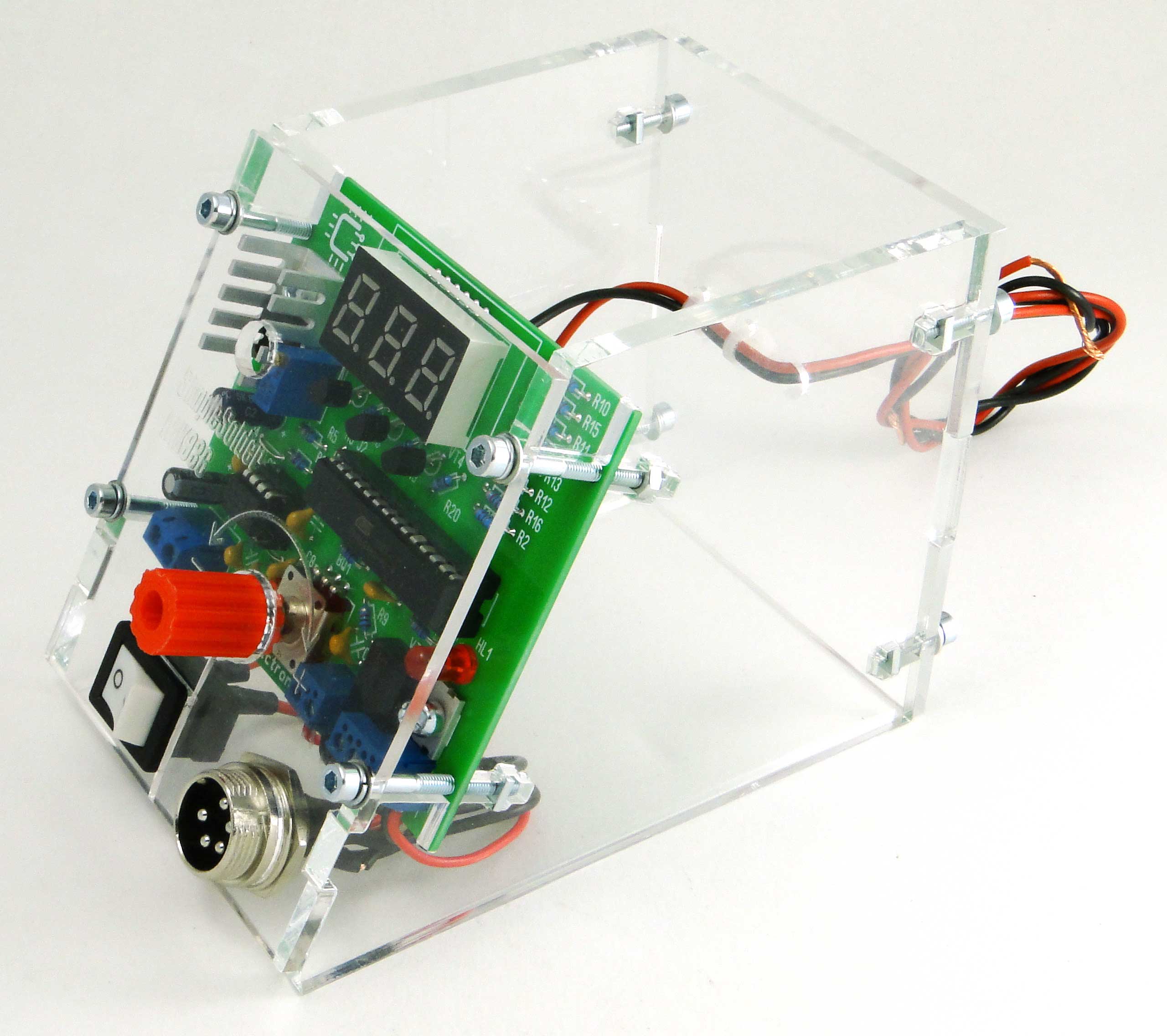
Housing for soldering station. Housing for soldering station based on Hakko T12. Housing assembly and volumetric installation
There are a lot of schemes of various soldering stations on the Internet, but they all have their own characteristics. Some are difficult for beginners, others work with rare soldering irons, others are not finished, etc. We have focused on simplicity, low cost and functionality so that every novice radio amateur can assemble such a soldering station.
What is a soldering station for?
An ordinary soldering iron that is connected directly to the network simply heats constantly with the same power. Because of this, it warms up for a very long time and there is no way to regulate the temperature in it. You can dim this power, but it will be very difficult to achieve a stable temperature and repeatable soldering.
Soldering iron prepared for soldering station has a built-in temperature sensor and this allows you to apply maximum power to it during heating, and then keep the temperature on the sensor. If you just try to regulate the power in proportion to the temperature difference, then it will either warm up very slowly, or the temperature will cyclically float. As a result, the control program must contain the PID control algorithm.
In our soldering station, of course, we used a special soldering iron and paid maximum attention to temperature stability.
Specifications
- Powered by a DC voltage source 12-24V
- Power consumption, when powered 24V: 50W
- Soldering iron resistance: 12ohm
- Time to reach operating mode: 1-2 minutes depending on the supply voltage
- Maximum temperature deviation in stabilization mode, no more than 5 degrees
- Control algorithm: PID
- Temperature display on a seven-segment display
- Heater type: nichrome
- Temperature sensor type: thermocouple
- Ability to calibrate temperature
- Setting the temperature with the ecoder
- LED for displaying the state of the soldering iron (heating / working)
circuit diagram
The scheme is extremely simple. At the heart of everything is the Atmega8 microcontroller. The signal from the optocoupler is fed to an operational amplifier with adjustable gain (for calibration) and then to the input of the ADC of the microcontroller. To display the temperature, a seven-segment indicator with a common cathode was used, the discharges of which are switched on through transistors. Turning the encoder knob BQ1 sets the temperature, and the rest of the time the current temperature is displayed. When enabled, the initial value is set to 280 degrees. Determining the difference between the current and required temperature, recalculating the coefficients of the PID components, the microcontroller heats up the soldering iron using PWM modulation.
To power the logic part of the circuit, a simple 5V DA1 linear regulator was used.

Printed circuit board
The printed circuit board is one-sided with four jumpers. The PCB file can be downloaded at the end of the article.


List of components
To assemble the PCB and case, you will need the following components and materials:
- BQ1. Encoder EC12E24204A8
- C1. Electrolytic capacitor 35V, 10uF
- C2, C4-C9. Ceramic Capacitors X7R, 0.1uF, 10%, 50V
- C3. Electrolytic capacitor 10V, 47uF
- DD1. ATmega8A-PU microcontroller in DIP-28 package
- DA1. L7805CV 5V stabilizer in TO-220 package
- DA2. Operational amplifier LM358DT in DIP-8 package
- HG1. Seven-segment three-digit indicator with a common cathode BC56-12GWA. The board also provides a seat for a cheap analogue.
- HL1. Any indicator LED for a current of 20mA with a pin pitch of 2.54mm
- R2,R7. Resistors 300 Ohm, 0.125W - 2 pcs
- R6, R8-R20. Resistors 1kOhm, 0.125W - 13pcs
- R3. Resistor 10kOhm, 0.125W
- R5. Resistor 100kOhm, 0.125W
- R1. Resistor 1MΩ, 0.125W
- R4. Trimmer resistor 3296W 100kOhm
- VT1. Field effect transistor IRF3205PBF in TO-220 package
- VT2-VT4. Transistors BC547BTA in TO-92 package — 3pcs
- XS1. Terminal for two contacts with a lead pitch of 5.08 mm
- Terminal for two contacts with a lead pitch of 3.81 mm
- Three-pin terminal with 3.81mm pin pitch
- Radiator for stabilizer FK301
- Block for housing DIP-28
- Socket for DIP-8 housing
- Power switch SWR-45 B-W(13-KN1-1)
- Soldering iron. We will write about it later.
- Plexiglas parts for the body (files for cutting at the end of the article)
- Encoder knob. You can buy it, or you can print it on a 3D printer. Model download file at the end of the article
- Screw M3x10 - 2 pcs
- Screw M3x14 - 4pcs
- Screw M3x30 - 4pcs
- Nut M3 - 2 pcs
- Nut M3 square - 8 pcs
- Washer M3 - 8 pcs
- Washer M3 groverny — 8 pieces
- You will also need mounting wires, ties and heat shrink tubing for assembly.
This is what the set of all parts looks like:

PCB mounting
When assembling a printed circuit board, it is convenient to use the assembly drawing:

The installation process will be shown in detail and commented on in the video below. We note only a few points. It is necessary to observe the polarity of electrolytic capacitors, LED and the direction of installation of microcircuits. Do not install microcircuits until the case is completely assembled and the supply voltage is checked. Chips and transistors must be handled with care to avoid damage from static electricity.
After the board is assembled, it should look like this:

Housing assembly and volumetric installation
The wiring diagram of the block looks like this:

That is, it remains only to bring power to the board and connect the soldering iron connector.
Five wires are required to be soldered to the soldering iron connector. The first and fifth are red, the rest are black. You must immediately put a heat shrink tube on the contacts, and tin the free ends of the wires.
Solder the short (from the switch to the board) and long (from the switch to the power supply) red wires to the power switch.
The switch and connector can then be installed on the front panel. Please note that the switch may be very tight. If necessary, modify the front panel with a needle file!


In the next step, all these parts are brought together. There is no need to install a controller, an operational amplifier and screw the front panel!

Controller firmware and setup
You can find the HEX file for the controller firmware at the end of the article. The fuse bits must remain factory, that is, the controller will operate at a frequency of 1 MHz from the internal generator.
The first inclusion should be made before installing the microcontroller and operational amplifier on the board. Apply a constant supply voltage from 12 to 24V (red should be "+", black "-") to the circuit and check that between terminals 2 and 3 of the stabilizer DA1 there is a supply voltage of 5V (middle and right terminals). After that, turn off the power and install the DA1 and DD1 chips in the sockets. At the same time, keep an eye on the position of the chip key.
Turn the soldering station back on and check that all functions are working properly. The temperature is displayed on the indicator, the encoder changes it, the soldering iron heats up, and the LED signals the operating mode.
The next step is to calibrate the soldering station.
The best option for calibration is to use an additional thermocouple. It is necessary to set the required temperature and check it on the tip using a reference instrument. If the readings differ, then adjust the multi-turn tuning resistor R4.
When setting up, remember that the indicator readings may differ slightly from the actual temperature. That is, if you set, for example, the temperature "280", and the indicator readings deviate to a small extent, then according to the reference device you need to achieve exactly the temperature of 280 ° C.
If there is no control measuring device, then you can set the resistance of the resistor to about 90 kOhm and then select the temperature empirically.
After the soldering station is checked, you can carefully install the front panel so that the parts do not crack.

Video of work
We filmed a short video review
…. And detailed video, which shows the build process:
I thought for a long time whether to write an article about this homemade product or not. On the Internet, you can probably count a dozen articles on this scheme. But since, in my opinion, this particular circuit solution is the most successful, I share the design with you, dear visitors of the Technoobzor website. I want to immediately thank the author of the scheme for the work done, and for the fact that he laid it out for common use. The soldering station is quite simple to manufacture and is very necessary in amateur radio practice.
When I first started my career as a radio amateur, I didn’t think about any. Soldered with a powerful 60 watt soldering iron. Everything was done by surface mounting and thick wires. Over the years, with a little experience, the tracks became thinner and the details smaller. Bought soldering irons of lower power, respectively. I somehow bought a soldering iron from a LUKEY-702 soldering station with a maximum power of 50 watts and a built-in thermocouple. I picked up the scheme for assembly right away. Simple and reliable, as well as a minimum of parts.
Scheme of a homemade soldering station


List of parts for the circuit:
- R1-1M
- R2 - 1k
- R3 - 10k
- R4-82k
- R5-47k
- R7, R8 - 10k
- R indicator -0.5k
- C3 - 1000mF/50v
- C2 - 200mF/10v
- C - 0.1mF
- Q1-IRFZ44
- IC4-78L05ABUTR


The power transformer was taken from a turntable. His name is TS-40-3. Didn't rewind anything. All the appropriate voltages are already on it. To power the soldering iron itself, two windings were connected in parallel. It produces about 19 volts. We have enough. To do this, on this model of the transformer, it is necessary to put jumpers between the transformer terminals 6 and 8, as well as 6 'and 8' on the other coil. Remove voltage from pins 6 and 6'.

To power the microcontroller of the soldering station control unit and the op-amp, we need a voltage of 7.5 to 15 volts. You can, of course, up to 35, but this will be the limit for the 78L05 stabilizer microcircuit. She will get very hot. To do this, I connected the windings in series. The voltage was 12 volts. Two wires are soldered to the 8th output of the transformer. Solder, which is thinner, and transfer it to a free terminal. The jumper must be placed on the 10th output of the transformer and the soldered wire. Voltage is removed from 10 'and 12 output. The above is only for the transformer TS-40-3.

Power diodes V1 are used by KD202K. Just right for this purpose. To power the MK, I took a small-sized diode assembly B2. E30361-L-0-8-W with a common cathode was used as LED indicators. I also spread my printed circuit board for my indicator. It turned out to be two-sided. Unilateral failed. Too many jumpers. The board is not the best, but tested and working. I also soldered the connector on the soldering iron itself. His standard is no good. At first, the booster was not provided on the board. I installed it after, but the board in the archive is fixed.


Picked up the best connector dad - mom from the available trash. I also want to say about the IRFZ44 field effect transistor. For some reason he didn't want to work with me. It burned out immediately when turned on. At the moment, IRF540 has been standing for about a year. Almost does not heat up. It doesn't need a big radiator.
Soldering station - case manufacturing

So, the body of the soldering station. It's good when you go to the store, and there is a choice of ready-made cases. Unfortunately, I don't have that luxury. And I don’t really want to look for all sorts of boxes from it’s not clear what, and then I still don’t really want to think about how to stuff everything there. The body was bent out of tin. After I marked and drilled all the holes and painted with spray paint. I sealed the indicator hole with a piece of plastic from a black beer bottle. The buttons are made from Soviet cases of KT3102 transistors in an iron case and the like. You also need to calibrate the temperature readings using the resistor R5 and the thermocouple of the multimeter. After assembling and checking, I secured all the wires with plastic fasteners. After screwing the top cover of the case. The station is ready to go. Happy assembly everyone. The soldering station was made by Bukhar.
Good afternoon, Dear Readers! Today we will talk about assembling a soldering station. So let's go!
It all started with the fact that I stumbled upon this transformer:
It is 26 volts, 50 watts.
As soon as I saw it, a brilliant idea immediately came to my mind: to assemble a soldering station based on this transformer. On Ali, I found this one. In terms of parameters, it is ideal - the operating voltage is 24 volts, and the current consumption is 2 amperes. I ordered it, a month later it came in shockproof packaging. In the picture, the sting burned a little, because I already connected the soldering iron to the transformer. I purchased the connector on the market, immediately with a connector for four wires.

But connecting the soldering iron directly to the transformer is too simple, uninteresting, and the tip will deteriorate so quickly. Therefore, I immediately began to think about the soldering iron temperature control unit.
At first, I thought over the algorithm: the microcircuit will compare the value from the variable resistor with the value on the thermistor, and, based on this, it will either supply current all the time (heating the soldering iron), or supply it in “packs” (temperature retention), or not supply it at all (when the soldering iron is not in use). For these purposes, the lm358 chip is perfect - two operational amplifiers in one package.
Soldering Station Regulator Diagram
Well, let's go directly to the scheme itself:
Parts list:
- DD1 - lm358;
- DD2 - TL431;
- VS1 - BT131-600;
- VS2 - BT136-600E;
- VD1 - 1N4007;
- R1, R2, R9, R10, R13 - 100 ohms;
- R3, R6, R8 - 10 kOhm;
- R4 - 5.1 kOhm;
- R5 - 500 kOhm (tuning, multi-turn);
- R7 - 510 Ohm;
- R11 - 4.7 kOhm;
- R12 - 51 kOhm;
- R14 - 240 kOhm;
- R15 - 33 kOhm;
- R16 - 2 kOhm (tuner);
- R17 - 1 kOhm;
- R18 - 100 kOhm (variable);
- C1, C2 - 1000uF 25v;
- C3 - 47uF 50v;
- C4 - 0.22uF;
- HL1 - green LED;
- F1, SA1 - 1A 250v.
Making a soldering station
At the input of the circuit there is a half-wave rectifier (VD1) and a current-quenching resistor.
Next, a voltage stabilization unit is assembled on DD2, R2, R3, R4, C2. This block lowers the voltage from 26 to 12 volts needed to power the microcircuit.

Then comes the control unit itself on the DD1 chip.

And the final block is the power part. From the output of the microcircuit, through the indicator LED, the signal goes to the triac VS1, which controls the more powerful VS2.

We also need a few wires with connectors. This is not necessary (the wires can also be soldered directly), but just right for Feng Shui.

For a printed circuit board, we need a textolite with dimensions of 6x3 cm.

We transfer the pattern to the board using the laser-ironing method. To do this, print out this file, cut it out. If something is not transferred, we finish it with varnish.
(downloads: 262)

Next, we throw the board into a solution of hydrogen peroxide and citric acid (3: 1 ratio) + a pinch of table salt (it is a catalyst for a chemical reaction).

When the excess copper dissolves, we take out the board, rinse it with running water

Then remove the toner and varnish with acetone, drill holes

And that's it! The printed circuit board is ready!
It remains to tin the tracks and solder the components correctly. Solder, focusing on this picture:

The following places must be connected with jumpers:

Yes, we have collected the fee. Now it would be necessary to place all this in the case. The base will be a square of plywood measuring 12.6x12.6 cm.

The transformer will be in the middle, fixed with screws on small wooden blocks, the board will “live” nearby, bolted to the base through the corner.
This circuit can also be powered by 12V, which makes it versatile. For this, it is necessary to exclude general scheme DD2,R2,R3,R4 and C2. Also, the thermistor in the circuit should be replaced with a constant resistor of 100 ohms.
This concludes my article. Good luck with your replay!
P.S. If the soldering iron does not start, check every connection on the board!
I wondered about making a case for this station. Of course, you can use the station in this form, but it is very dangerous for the station itself (the boards can short each other out if accidentally touched) and for the people around.
As options for making the case, I considered the following ideas:
- Print on a 3D printer
- cut into pieces of any flat material(acrylic, laminate, chipboard) and assemble from pieces
- Adjust the box to fit
The first two options involve careful preparation in the form of case design, and the third comes down to simply finding a box. right size, A New Year already on the nose and I want to start the soldering station as soon as possible, so for now I decided to try the third way, and then, if I don’t like it, I’ll redo it!
If you are a very greedy person, then you can use plastic packaging from Korean carrots or salted herring as a case, but it will look much more beautiful Plastic container, purchased at the Wholesaler or at Jupiter.
I found a suitable size container, laid out the boards inside it so that they did not touch each other. I attached the plugs, shield and potentiometers to their future places, checked that they did not touch the boards. I made holes for the protruding elements with a drill, if they were required to be round, and with a scalpel heated on fire, if of a different shape. The GX-16 plugs and the 220v input wire socket with a fuse had to be disconnected from the board, as they are inserted into the holes from the OUTSIDE! At the same time, do not mix up the wires when connecting them in place! The boards inside were fixed with hot glue, but later I'm going to add a more secure fastening to them - with cable ties or metal screws.
And after assembling the device in the case, I randomly found that the resulting design in a 191x129mm plastic box fits perfectly on the bottom level of a standard 12-inch tool container! Thus, on the upper level of the same container, you can store a hair dryer and a soldering iron disconnected from the soldering station, and solder and other soldering accessories on the remaining part of the lower level!
I will not describe each step of manufacturing and assembly, instead I suggest that you familiarize yourself with the photo report. As they say, it's better to see once!
How to arrange components? Arranging the components Trying on The top shelf will store the hair dryer and soldering iron External elements are already embedded Screen and potentiometers in place Switch and fuse GX-16 Trial operation Checking the soldering iron Future storage location Box dimensions are printed on the lid 12-inch case Top shelf
For some time I used a soldering station based on the Hakko T12 controller. I tried to make a case for the station myself, but my inner perfectionist did not approve of a gray boring box with crooked slots, so for some time my station existed without a case in a small cardboard box, and it so happened that at one “perfect” moment, unsuccessfully hitting controller, I burned something in it. Therefore, I decided that I needed a station in the building. T12 suited me completely, and I began to look at complete stations, such as . But the prices did not suit my toad, especially since the PSU and the handle are already there, so I ordered the case separately and without the handle for $9.08.
Read on to see what came out of it.
Delivery ◄
The goods were paid for on March 12. The RI************CN format track was issued on March 14, and on March 28 I ran to the post office to pick up my package. Two weeks after sending, for me this is one of the fastest parcels, I don’t know who to thank for this, probably, after all, the Russian Post. The controller ordered on the same day arrived on April 4, which is also quite good, usually I wait at least a month, I hope the PR will continue to please me.There will be no photo of the packaging, but please, here are the insides:

The edges are not covered with a pimple, and although the envelope inside was also pimpled, it would be better to wrap the whole case all the same.
First impressions ◄
Upon receiving the parcel, I was a little scared, because I expected that the envelope was thicker. I use a PSU 30 mm high, and the envelope with the bubble wrap was only 3 cm thick. But having opened the envelope, I calmed down, since the case consists of two parts, 19 mm each. Having tried on all the elements to the body, I finally calmed down - everything is included.I liked the design of the case, it looks neat and strict, it is conveniently opened for prevention and inspection of the insides. I don't think there are enough ventilation holes.
Compound:
- 1. Identical bottom and top housing with slots.
- 2. Front and back walls.
- 3. IEC C6 socket.
- 4. Button on / off.
- 5. Eight black screws for fixing the walls.
- 6. Two white screws to secure the IEC socket.
- 7. Four anti-slip rubber feet.

Additional pictures with dimensions


Assembly ◄
For a person who has a similar controller, assembling this case should not be something difficult. Therefore, there is nothing particularly interesting here. But, just in case, I will describe the sequence of my actions.- 1. We fasten the IEC C6 connector, aka Mickey Mouse, to the back wall of the case.
- 2. Insert the power button.
- 3. We solder the wiring.
- 4. We place the PSU on one of the halves of the case (they are identical, so choose any). As insulation under the PSU, I used a piece from a plastic envelope.
- 5. We connect or solder the wires to the PSU (I used standard terminals).
- 6. We fasten the back wall to the lower half of the case with complete screws.
- 7. Go to the front wall. We insert the aviation connector into the corresponding hole. Put a washer on the reverse side and screw on the nut. I don’t recommend tightening it right away, because you may have to move the controller a little so that the indicator is flush with the window.
- 8. I did not immediately solder the diode, I just placed it in the intended holes on the board.
- 9. Insert the encoder knob into the corresponding hole, align the holes on the board with the legs of the aviation connector and screw the nut onto the encoder knob.
- 10. Making sure that the indicator is located strictly in the center of the window, we alternately tighten the nuts of the encoder and the aviation connector.
- 11. Align and pull the diode into the hole as much as possible and solder it to the controller.
- 12. Solder the aviation connector to the controller.
- 13. We connect or solder the power wiring from the controller to the power supply unit (this time I soldered it, since I soldered the standard terminals, placing this unit in a makeshift case).
- 14. We fasten the front wall to the lower half of the case.
- 15. Further, along the edges of the PSU, I filled it with hot-melt adhesive so that it would not crawl along the case. In terms of height, there would be enough space for the legs, but the corners of the PSU board were sawn off in the process of creating the first case, so there was nothing to screw to.
- 16. Close the lid on top and fasten the remaining screws and glue the rubber feet to the bottom.
- PROFIT!!!

Results ◄

It's time to take stock.
Compact.
+ Easy assembly.
+ Neat appearance.
The first thing I didn’t like right away was the IEC C6 connector, it would be better if they made a traditional C14.
-The thread is not cut very evenly, so the screws are tightened with force and slightly at an angle, it does not catch the eye, but this limits the number of assembly and disassembly cycles, the slots and threads wear out quickly (by the way, when screwing, do not immediately screw the screws to the full, it is better slightly screw in turn).
-No ventilation holes. I'm not sure if they're needed, but they certainly wouldn't hurt.
-Absent protective window for the indicator, you can do something, even with a light filter, but I was too lazy to do it.
-In connection with the previous paragraph, there are small inconsistencies between the indicator and the window under it.
-Both halves are the same. On the one hand, it’s good, you don’t have to think about which one goes where, but on the bottom half, the embossed stripes make it difficult to stick the rubber legs in the right places. For better contact, it is better to mount them on a smooth surface, and this is either on the outside of the strips - i.e. too close to the edges, or on the inside too close to the center. I hope it's clear what I mean.
-I would like a U-shaped leg (I don’t know what it’s called correctly), to fix the station at an angle.
- Lack of spare screws, at least a couple could be put.
-Coloring. I checked it on the internal parts, it peels off from slight touches of sharp objects, which means that with intensive use of the device, the case will quickly peel off.
± Price. For whom, how, I think the price is ~ 1000 rubles. quite acceptable for the body, tk. even simple plastic boxes I have offline cost at least 350r (I didn’t even consider any distribution boxes, my inner perfectionist said - “POORITY”).
Despite the abundance of minuses, I was satisfied with the case, especially since most of them can be corrected. Would I buy it again? Yes!
About the controller
I can’t say for sure what happened to the previous controller, because I didn’t deal with it, either I closed the contacts, or the smd capacitor overheated. As a result, when the power is connected, the numbers 0 and 500 change cyclically on the indicator, while the sting quickly overheated and turned blue. When I have free time I will try to restore this controller. In the meantime, I'll try a new one. The burnt one is slightly different from the new one, the burnt one is marked STC T12-HG, on the new MINI STC T12 VER:A (it seems like a new one, this is an earlier version, sorry for the pun :)).
Burnt controller on the right. 
The place on the burnt controller where I poked with a sting: 
New controller complete set: 
The new board suits me perfectly, the tracks are not cut anywhere. All menus are available. There are enough reviews on this controller here, so I will not describe it in detail.


